Calculation and Design Guide for Heating Coils in Storage Tanks
Ing. José Félix Acevedo B.
5/12/20257 min read
1. Introduction
Heating coils are systems used in storage tanks to maintain the temperature of viscous products such as fuel oils, asphalts, greases or waxes, allowing them to be pumped or processed. Proper design is essential to preserve the physical properties of the product, prevent solidification, and ensure operational efficiency.
This guide presents the fundamentals for heat duty calculation, pipe sizing, and the most common mistakes to avoid during thermal and mechanical design.
2. Purpose of the coil system
Avoid solidification or excessive increase in viscosity of the stored product.
Maintain optimal operating conditions for pumping or mixing.
Compensate for thermal losses from the tank to the environment.
3. Key Design Variables
🔥 Required operating temperature of the product.
🌡️ Design minimum ambient temperature (typically the lowest external temperature of the year).
🛢️ Tank volume and geometry (diameter, liquid height, bottom geometry).
💧 Heating fluid type: steam, hot water, thermal oil.
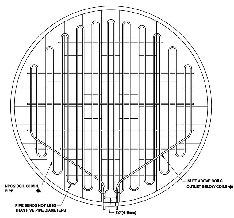
🔁 Configuration of the coils: bottom, sides, or both.
4. Heat Duty Calculation
Heat duty is the amount of energy that must be transferred to the product to reach or maintain its operating temperature. It can be expressed in two ways, depending on the case:
To keep the temperature constant and compensate for thermal losses:
Q = U ⋅ A ⋅ ΔTml
· To raise the temperature of the product:
Q = m ⋅ Cp ⋅ ΔT/t
Where:
· Q: Thermal Load [W]
· U: global heat transfer coefficient [W/m²·°C]
· A: Exchange area [m²]
· Δ T_ml: logarithmic mean temperature difference [°C]
· m: mass of the product to be heated [kg]
· Cp: heat capacity of the product [kJ/kg·°C]
· ΔT: Temperature difference between fluid or product inlet and outlet [°C]
· t: Time required to heat the product [s]
💡 Note: The coefficient U depends on the type of fluid, flow rate, flow rate (laminar or turbulent), coil material, and internal/external fouling.
For a detailed explanation of the heat duty calculation, you can refer to this complementary guide: 🔗 Calculating Heat Duty in Tanks
5. 1. How is the logarithmic mean temperature difference calculated?
ΔTml = [(Th,i−Tc,o)−(Th,o−Tc,i)]/ln[(Th,i−Tc,o)/(Th,o−Tc,i)]
Where:
T_{h,i}: hot fluid inlet temperature
T_{h,o}: hot fluid outlet temperature
T_{c,i}: Product inlet temperature
T_{c,o}: product outlet temperature
🔁 In the case of steam (isothermal process):
ΔT = Tvapor−Tproducto
6. Data required for design
6.1 Stored product (outside of the coil):
Specific gravity
Absolute viscosity
Thermal Conductivity
Specific heat
Volumetric expansion coefficient
Fouling resistance
6.2 Heating fluid (inside of the coil):
Available pressure and temperature
Saturation temperature (if steam)
Enthalpy of vaporization (if steam)
Specific gravity or Specific volume (if steam)
Specific heat
Thermal Conductivity
Absolute viscosity
Fouling resistance
7. Types of Heating Fluid and Selection Criteria
7.1 Water Vapor (saturated)
Steam is widely used for its high heat transfer capacity due to its latent heat of condensation. Steam is usually available at temperatures between 120 and 180°C. It is considered an isothermal process because the steam gives up energy by condensing at a constant temperature. When entering the coil as saturated steam, it is assumed that when it leaves it has already condensed completely, becoming a saturated liquid, without energy losses due to overheating or subcooling.
The heat transferred in this case is:
Q = ṁvapor ⋅ λ
Where:
· ṁ: Mass flow of the fluid [kg/s]
· λ: is the latent heat of condensation of the steam [J/kg].
Usage Criteria:
Ideal when a steam network is available.
High efficiency for highly viscous products.
The pressure of the steam determines the heating temperature.
Requires condensate control and steam traps.
Coil material must withstand operating pressure (often 3–10 bar).
7.2 Thermal Oil
Thermal oil is used when temperatures above 180–200 °C are required or steam is not available. Unlike steam, oil does not change phase and transfers heat due to its sensible heat:
Q = ṁ ⋅ Cp ⋅ (Tinlet−Toutlet)
Where:
ṁ: Mass flow of the fluid [kg/s]
Cp: specific heat of the fluid [J/kg· °K]
Tinlet, Toutlet: Thermal oil temperatures [°C or °K]
Usage Criteria:
Recommended for products that require constant and controlled high temperatures.
It works in closed and pressurized systems.
Increased safety in areas without steam infrastructure.
Fire Hazard: Requires detection systems and relief valves.
It can degrade thermally if it exceeds its limit temperature.
Increased circulating fluid volume and high-temperature resistant pumps.
7.3 Hot Water
Hot water is used when the required temperature difference is moderate (less than 50 °C) and the product does not require high temperatures. Heat is transferred by sensible heat, just like with thermal oil.
Usage Criteria:
Economical and safe.
Temperature limit: maximum ~95°C for open systems, up to ~130°C if pressurized.
Low transfer capacity compared to steam.
It requires larger coil areas to achieve the same effect.
Recommended for light oils or products with low solidification point.
8. Preliminary pipe diameter selection
Before applying the heat transfer equations, it is necessary to select an initial pipe diameter that guarantees an adequate flow (usually turbulent) and allows the correct calculation of the Reynolds number.
The following formula is used to estimate a preliminary diameter based on the mass flow and desired velocity:
Di = [4 ⋅ ṁ/(π ⋅ ρ ⋅ v)]1/2
Where:
· Di: Pipe Inside Diameter [m]
· ṁ: Mass flow of the fluid [kg/s]
· ρ: fluid density [kg/m³]
· V: Recommended fluid velocity [m/s]
Typical speed values:
· Agua caliente: 1.0 a 2.5 m/s
· Thermal oil: 0.5 to 1.5 m/s
· Vapor: 15 a 35 m/s
This Di value is then used in the equations to determine the flow regime, the Reynolds number, and subsequently the heat transfer coefficient.
9. Calculation of Thermal Coefficients and Dimensionless Numbers
9.1 Reynolds Number (D):
Re = ρ ⋅ v ⋅ D/m
Where:
· ρ: density [kg/m³]
· V: Velocity [m/s]
· D: diameter [m]
· μ: viscosity [Pa·s]
9.2 Grashof number (Gr)
Used in cases where natural or mixed convection is relevant, especially on the outer side of the coil when the heated fluid is at rest (such as in tank fluid).
Gr=g⋅β⋅(Ts−Tfluid)⋅Do3/ν
Where:
g: Gravitational acceleration [m/s²]
β: volumetric expansion coefficient [1/K]
Ts: Tube Surface Temperature [K]
Tfluid: Tank Fluid Temperature [K]
Do: Pipe Outside Diameter [m]
ν: kinematic viscosity [m²/s]
9.3 Prandalt number (Pr)
Pr = Cp ⋅ μ/k
Where:
Cp: specific heat of the fluid [J/kg· °K]
μ: Dynamic viscosity [Pa·s]
k: thermal conductivity of the fluid [W/m·°K]
This number compares how fast motion (viscosity) versus heat (thermal conductivity) is transmitted in a fluid. It is critical for calculating convection heat transfer.
9.4 Nusselt Number (Nu)
· For forced convection:
In coils forced convection usually occurs on the inner side of the tubes, in this case the Nusselt number depends on the Reynolds and Prandalt numbers and is calculated according to the following equation:
Nu = 0.023 ⋅ Re0.8 ⋅ Prn (n=0.4 when heating, n=0.3 when cooling)
For natural convection:
In coils natural convection normally occurs on the outer side of the tubes, in the case of natural convection the Grashof number is combined with Prandalt to calculate the Nusselt number in natural convection:
Nu = C ⋅ (Gr⋅Pr)n
For horizontal tubes (cylinders):
Si 104<Gr⋅Pr<109;
o n = 1/4
o C = 0.47 for small tubes (day ≤ 1")
o C= 0.53 for large pipes (dia > 1")
Si 109<Gr⋅Pr<1012: C = 0.13, n = 1/3
9.5 Film coefficient.
Internal Coefficient:
hi = Nu ⋅ ki /Di.
External coefficient:
ho = Nu ⋅ ko /Do.
Where:
Nu: Nusselt number
Di: Pipe Inside Diameter [m]
Do: Pipe Outside Diameter [m]
ki: Thermal conductivity of the fluid inside the tubes [W/m·°C]
ho: Thermal conductivity of fluid outside tubes [W/m·°C]
10. Overall heat transfer coefficient (U)
1/U = 1/hi + Rf,in + Rf,out + Rw + 1/ho
h_i: Internal coefficient [W/m2·°C]
h_o: External coefficient [W/m2·°C]
R_{f,in}, R_{f,out}: internal and external fouling resistances [m²·°C/W]
Rw = Pipe wall resistance [m²·°C/W]
11. Fouling Resistance
Typical reference values:
Clean Vapor: 0.0001–0.0002 m²·°C/W
Thermal oil: 0.0004–0.0008 m²·°C/W
Clean water: 0.0002–0.0004 m²·°C/W
Heavy fuel oils: 0.001–0.002 m²·°C/W
Dirty products: up to 0.003 m²·°C/W
⚠️ These values must be adjusted according to experience, standards (such as TEMA) and real conditions.
12. Tube Wall Resistance (Rw)
The thermal resistance of the tube wall, Rw, can be calculated using the cylindrical conduction-based formula:
Rw = ln(Do/Di) · Do / (2 · khc)
Where:
Do: Pipe Outside Diameter [m]
Di: Pipe Inside Diameter [m]
khc: Pipe material thermal conductivity [W/m·°C]
13. Calculating the Length of the Coil
A = Q / (U ⋅ ΔTml), for thermal oil and/or hot water
A = Q / (U ⋅ ΔT), for water vapor (steam)
L = A / (π ⋅ Do)
Where:
Q: Thermal load (Heat dutyu) [W]
U: Global heat transfer coefficient [W/m2·°C].
ΔTml: Mean logarithmic temperature difference [°C].
ΔT = Tvapor - Tproduct
Do: Pipe Outside Diameter [m]
14. Recommended Materials for Coils
Carbon steel: economical, commonly used with steam and hot water.
Stainless steel (304/316) – corrosion resistant, ideal for thermal oil.
Special alloys (Incoloy, Hastelloy): for extreme conditions.
Pipingclass and customer specifications: Check the recommended materials in the customer's specifications
Considerations:
Product and fluid compatibility
Operating temperature and pressure
Maintenance and durability expected
15. Common design errors
❌ Split coils in parallel without redesign:
If branches are duplicated without reducing the diameter or recalculating Re, Pr, Nu, the flow can become laminar, decreasing thermal efficiency.
✅ Solution:
Adjust the diameter and recalculate all the parameters for each branch.
❌ Not considering fouling:
Omitting this resistance leads to overestimating the actual thermal capacity.
❌ Underestimating the minimum ambient temperature:
It can cause the system to fail to perform its function in winter.
❌ Not providing access or maintenance:
Lack of purges, drains or registers complicates operation and cleaning.
✅ General recommendation:
Design with the most demanding conditions, maintenance and safety margins in mind.
16. Design recommendations
✅ Improve insulation if there is not enough space inside the tank for the required length
✅ Avoid low-traffic dead zones
✅ Include bleed and drain valves (outside the tank)
✅ Verify compatibility of materials and operating conditions
17. Conclusion
The design of tank heating coils is a multidisciplinary task that requires careful integration of the system's physical properties, heat transfer analysis, flow behavior, and practical operation and maintenance considerations.
Correctly applying these criteria ensures thermal efficiency, operational safety, durability and a long service life of the system.
18. Glosary of Terms
Exchange area (A): The outer surface of the tubes through which heat is transferred between the hot fluid and the product.
β: Volumetric expansion coefficient of the fluid.
Cp: Specific heat of the fluid, amount of energy required to raise one kilogram of fluid by one degree Celsius.
Di: Pipe inside diameter.
Do: Pipe outside diameter.
ΔT: Temperature difference between fluid or product inlet and outlet
ΔTml: Mean logarithmic difference between hot fluid and product temperatures, used to estimate net heat transfer.
Mass flow (ṁ): The amount of mass of fluid circulating through the coil per unit of time.
Grashof (Gr): A dimensionless number representing the relationship between buoyant forces and viscosity in natural convection.
hfg: Enthalpy of vaporization of saturated vapor.
hi: Internal film coefficient of the heating fluid inside the tube.
ho: Coefficient of external film between the surface of the tube and the stored product.
k: Thermal conductivity of the fluid.
λ: Latent heat of condensation of the steam.
μ: Dynamic viscosity of the fluid.
Nusselt (Nu): A number that relates convection to thermal conduction; allows estimating the film coefficient.
Prandtl (Pr): A number that relates the viscosity and thermal conductivity of the fluid.
Heat Duty (Q): The amount of thermal energy required to maintain or raise the temperature of a product in the tank.
Reynolds (D): Dimensionless number that allows determining whether the flow is laminar or turbulent.
Rf: Resistance due to fouling, internal and external.
Rw: Thermal resistance of the pipe wall, calculated based on its thickness and conductivity.
Global coefficient (U): A value that integrates all thermal resistances (internal, external, wall, and fouling) and represents the total efficiency of heat exchange.
v: Velocity of the fluid inside the tube.
ν: Kinematic viscosity of the fluid.
ρ: Fluid density.
Details
engineering
info@aceinteca.com
© 2024. All rights reserved.
Technical Information for Tank Equipment Courtesy of World Bridge Industrial Co. Ltd.
Technical Information for Tanks Protection Devices Courtesy of Korea Steel Power Corp.
Technical Information for Bolted Tanks Courtesy of Center Enamel.
Glass Fused Steel Bolted Tanks
Stainless Steel Bolted Bolted Tanks
Aluminum Suspended Deck for Cryogenic Tanks.
Aluminum Rolling Ladder for External Floating Roofs
WhatsApp +58 416 6289796