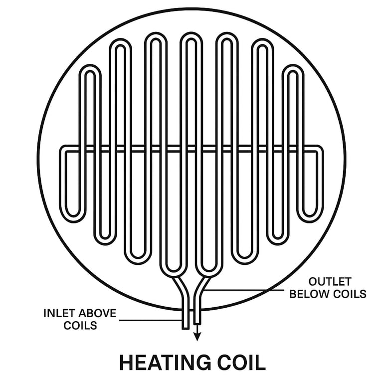
Preliminary Design of Bottom Heating Coils in Storage Tanks; Flowrate, Diameter, Length and Pressure Drop
Ing. José Félix Acevedo B.
5/13/20253 min read
1. Introduction
In the design of heating systems for storage tanks containing viscous fluids, the bottom heating coil plays a vital role in maintaining the product within its required operating temperature range. This blog provides a practical guide for pre-sizing these coils once the heat duty has been determined, covering the calculation of required flowrate, internal diameter, heat transfer area, estimated coil length, and pressure drop, depending on the heating medium used: saturated steam, thermal oil, or hot water.
2. What parameters do we need to know?
Before starting the calculations, it is essential to know:
Q (Heat Duty): The thermal load required to maintain or raise the product temperature.
Product temperature and heating fluid temperature.
Physical properties of the heating fluid, such as viscosity, thermal conductivity, specific heat, and density.
Operating conditions: including operating pressure, maximum coil temperature, and any space constraints
.
3. Mass Flowrate of the Heating Fluid
For thermal oil and hot water:
ṁ =Q / (Cp ⋅ ΔT)
Where:
ṁ: mass flowrate [kg/s]
Q: heat duty [W = J/s]
Cp: specific heat capacity [J/kg·°C]
ΔT: temperature difference between inlet and outlet of the heating fluid [°C]
Typical values:
Cp of hot water ≈ 4180 J/kg·°C
Cp of thermal oils ≈ 1800 to 2400 J/kg·°C
ΔT: 10–20 °C for thermal oil, 5–15 °C for hot water
Source: Eastman Therminol™, Perry’s Handbook
For saturated steam:
In this case, as it is an isothermal process (condensation at constant temperature), the following applies:
🔎 Technical note: This steam formula assumes single-phase flow prior to condensation. In practice, part of the coil can operate in a two-phase mode if the steam condenses before leaving. For conservative predesign, it can be assumed that most of the coil operates in vapor flow.
ṁ = Q / λ
Where:
λ: latent heat of condensation [J/kg], typically 2,257,000 J/kg at 100 °C
Source: IAPWS Steam Tables (2021)
4. Internal Pipe Diameter Calculation
Vm = ṁ / ρ,
Di = [4 ⋅ Vm / (π ⋅ v)]^1/2
Reynolds number must also be verified:
Re = ρ ⋅ v ⋅ Di / μ (turbulent if Re>4000)
Where:
Vm: volumetric flowrate [m³/s]
ṁ: mass flowrate [kg/s]
ρ: fluid density [kg/m³]
Di: Internal diameter [m]
v: average velocity [m/s]
μ: viscosity [Pa·s]
📌 Recommended design velocities for coil flow ensure turbulent regime, reduce fouling, and optimize heat exchange:
For hot water: 1.0 to 2.5 m/s (source: Perry’s Chemical Engineers’ Handbook, 8th ed.)
For thermal oil: 0.5 to 1.5 m/s (source: Coulson & Richardson’s Chemical Engineering Design, Vol. 6)
For saturated steam: 10 to 35 m/s (source: Crane Technical Paper No. 410 – Flow of Fluids)
In practice, coils are typically built using carbon steel or stainless steel pipes. The nominal pipe diameters vary depending on the heating fluid and thermal load:
For saturated steam, although 1" and 1.5" pipes are common, diameters greater than 1.5" are frequently used for larger heat duties or lower pressure drop.
For thermal oil and hot water, it is common to use 2", 2.5", or even larger than 3" pipes when higher flowrates or lower velocity (hence lower friction) are required.
Choosing the proper pipe size has a direct impact on the coil length, thermal efficiency, and maintenance accessibility.
5. Logarithmic Mean Temperature Difference (LMTD)
ΔTlm = [(Thi−Tco)−(Tho−Tci)]/ln[(Thi−Tco)/(Tho−Tci)]
Where:
Thi: hot fluid inlet temp
Tho: hot fluid outlet temp
Tci: cold fluid (product) inlet
Tco: cold fluid outlet
6. Coil Surface Area and Length
A = Q / (U ⋅ ΔTlm).
L = A ⋅ (1 + SF) / (π ⋅ Do)
Where:
Q: Head Duty [w]
U: Overall heat transfer coefficient [W/m²·°C]
ΔTlm: Logarithmic mean difference in temperature [°C]
A: Heat transfer area [m²].
SF: Safety Factor (10%)
L: Length of coil pipe [m].
Do: Head coil Pipe Outside Diameter [m].
Typical overall heat transfer coefficients U:
Steam: 400–800 W/m²·°C
Thermal oil: 150–400 W/m²·°C
Hot water: 300–600 W/m²·°C
Source: Kern, Perry’s, Coulson & Richardson
7. Pressure Drop Calculation
For water and oil (Darcy-Weisbach):
ΔP = f ⋅ L ⋅ ρ ⋅ v^2 / (2 ⋅ Di)
Where:
ΔP: pressure drop [Pa]
f: friction factor
L: pipe length [m]
Di: internal diameter [m]
ρ: density [kg/m³]
v: velocity [m/s]
Source: Crane Technical Paper No. 410
Typical allowable drops:
Hot water: ≤ 0.5 bar
Thermal oil: ≤ 1.0 bar
For saturated steam:
ΔP = 0.6753×10^6 ⋅ ṁ^2 ⋅ L ⋅ (1+91.4/Di) / (ρ ⋅D^5)
Where:
ṁ: Steam mass flow [kg/hr]
Di: Internal pipe diameter [mm]
ρ: Steam density [kg/m³]
L: Pipe length [m]
Source: Kern, D.Q. – Process Heat Transfer, McGraw-Hill (1950)
Application conditions: turbulent steam, before condensation, horizontal pipe, standard carbon steel roughness.
Recommended drop: ≤ 0.3 bar
8. Design Notes
If the calculated pressure drop is excessive or coil length is impractical, consider the following:
Use a larger diameter to reduce velocity and friction
Recalculate the heat duty using a thicker insulation layer
Select an insulation with lower thermal conductivity to reduce energy losses
9. Conclusion
Designing bottom heating coils is a critical task that combines heat transfer principles with fluid dynamics. A robust pre-design—based on consistent SI units, flow regime verification, and careful control of pressure drop—ensures an efficient, safe, and cost-effective system. Adapting parameters according to the heating fluid and insulation quality leads to optimized solutions in performance, operating cost, and maintainability.
Details
engineering
info@aceinteca.com
© 2024. All rights reserved.
Technical Information for Tank Equipment Courtesy of World Bridge Industrial Co. Ltd.
Technical Information for Tanks Protection Devices Courtesy of Korea Steel Power Corp.
Technical Information for Bolted Tanks Courtesy of Center Enamel.
Glass Fused Steel Bolted Tanks
Stainless Steel Bolted Bolted Tanks
Aluminum Suspended Deck for Cryogenic Tanks.
Aluminum Rolling Ladder for External Floating Roofs
WhatsApp +58 416 6289796