How to Correctly Calculate the Wind Vector in Engineering Applications
Ing. José Félix Acevedo B.
1/5/20261 min read
1. Introduction
In multiple engineering applications such as the analysis of the range of water jets or water-foam, dispersion studies, industrial ventilation and fire protection, it is essential to correctly interpret the wind direction and transform it into a physical vector that can be used in calculations.
2. Wind Direction Weather Convention
Wind direction is always defined as the direction WHERE the wind is coming from, and not where it is headed.
Examples:
North wind (N): comes from the north and blows south.
East wind (E): comes from the east and blows westwards.
ENE wind: comes from the east-northeast and blows west-southwest.
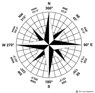
3. Reference System and Azimuth
The azimuth system is used with a northerly origin (0°) and a clockwise direction.
N: 0°
NNE: 22.5°
NE: 45°
ENE: 67.5°
E: 90°
ESE: 112.5°
SE: 135°
SSE: 157.5°
S: 180°
SSW: 202.5°
SW: 225°
WSW: 247.5°
W: 270°
WNW: 292.5°
NW: 315°
NNW: 337.5°

4. Wind Direction vs Wind Vector
The wind vector represents the actual direction in which the air is moving and is obtained by reversing the meteorological direction by 180°.
5. Calculating the Angle of the Wind Vector
For θ_direction + 180° < 360°
θ_w = θ_direction + 180°
For θ_direction + 180° ≥ 360°
θ_w = θ_direction − 180°
6. Practical Examples
Wind ENE: Direction: 67.5° → Wind vector: 247.5°
Wind SSW: Direction: 202.5° → Wind vector: 22.5°
7. Use in Engineering Calculations
The wind vector is used to calculate the wind components parallel and perpendicular respect to an axis of interest.
V∥ = V_w · cos(Δθ)
V⊥ = V_w · sin(Δθ)
Where Δθ = θ_w – θj
θj = Monitor azimuth
8. Final Recommendations
Always convert the weather direction to wind vector before performing calculations.
Details
engineering
info@aceinteca.com
© 2024. All rights reserved.
Technical Information for Tank Equipment Courtesy of World Bridge Industrial Co. Ltd.
Technical Information for Tanks Protection Devices Courtesy of Korea Steel Power Corp.
Technical Information for Bolted Tanks Courtesy of Center Enamel.
Glass Fused Steel Bolted Tanks
Stainless Steel Bolted Bolted Tanks
Aluminum Suspended Deck for Cryogenic Tanks.
Aluminum Rolling Ladder for External Floating Roofs
WhatsApp +58 416 6289796