Guide for Sizing Stilling Well Pipes for Measurement and Sampling Systems
Ing. José Félix Acevedo B.
6/21/20252 min read

Introduction
This technical guide defines the design and sizing criteria for stilling wells (also known as gauge wells or guide poles) in vertical storage tanks, whether fixed-roof or floating-roof types. It is especially useful in the absence of specific requirements from the instrumentation discipline. The criteria outlined herein are based on ExxonMobil’s Global Practice GP 09-07-01.
Stilling Well Pipes Main Functions
Prevention of Floating Roof Rotation: In tanks with internal or external floating roofs, the stilling well functions as an anti-rotation device, preventing the roof from turning due to turbulence or wind. This protects drain systems, rolling ladders, and automatic gauges from damage.
Level Measurement (Manual and Automatic): Acts as a guide for radar or servo instruments and allows manual gauging with a tape and plumb bob.
Product Sampling: Provides safe access for thief-type samplers.
Temperature Monitoring: Allows vertical installation of temperature probes for monitoring the liquid’s thermal profile.
Standard Dimensions for Stilling well Pipes and Guide Poles
A diameter of 8" NPS is recommended for the stilling well pipes used in level and capacity measurement systems, but it will depend on the requirements of the instrument to be used. In the case of guide posts for floating roofs, their diameter depends on the diameter of the tank, and larger diameter stilling well pipes can be used, e.g. 10", 12" and 14".
Stilling Well Pipes Configuration
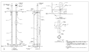
The stilling well must be fabricated from carbon steel with a minimum standard thickness (Schedule Std), free of burrs. It should include holes or slots along its entire length.
In the absence of specific instrumentation requirements, or when used for sampling or manual gauging, the following configurations are recommended:
Slot design: Slots should be 1½” × 6” (40 × 160 mm), arranged in two opposite, staggered rows, spaced approximately 18” (460 mm) apart. For floating roof guide poles, they should be oriented at 45° to the roller contact points.
Hole design: Holes should be at least 1” (25 mm) in diameter, or as required by the instrument. They should be arranged in two opposite, staggered rows, spaced approximately 600 mm apart, and also oriented at 45° to the roller contact points.
At least one slot or hole must be located above the maximum liquid level. If this level is unknown, the uppermost opening should be no more than 300 mm from the top edge of the tank shell.
Stilling Well Pipes Location
For floating roof tanks, they must be located at a minimum radial distance of 915 mm from the tank wall.
For tanks without a floating roof, the radial distance between the tank wall and the center of the pipe should be at least 610 mm
Stilling Well Pipes for Temperature Probes
The recommended minimum diameter is 2 inches NPS, unless otherwise required. The pipe should include 19 mm holes in two opposite, staggered rows spaced every 600 mm. These temperature wells are typically secured to the main stilling well using ¾” plain rods for increased rigidity.
Emission Control in External Floating Roof Tanks
For volatile products such as gasoline, it is recommended to install a vapor-sealed sleeve around the slotted stilling well to minimize fugitive emissions and comply with environmental regulations such as those from the US EPA. Solutions like the Vapor Guard® Gauge Pole Cover or Gauge Pole Ladder Cover effectively reduce emissions and can be installed in existing tanks without interrupting storage operations.
Safety and Installation Recommendations
The lower end of the stilling well must not be welded to the tank bottom to allow vertical movement with the floating roof.
The topmost slot or hole must always be located above the maximum operating level.
When an automatic gauge is installed, a separate stilling well should be considered for manual gauging and/or product sampling.
Details
engineering
info@aceinteca.com
© 2024. All rights reserved.
Technical Information for Tank Equipment Courtesy of World Bridge Industrial Co. Ltd.
Technical Information for Tanks Protection Devices Courtesy of Korea Steel Power Corp.
Technical Information for Bolted Tanks Courtesy of Center Enamel.
Glass Fused Steel Bolted Tanks
Stainless Steel Bolted Bolted Tanks
Aluminum Suspended Deck for Cryogenic Tanks.
Aluminum Rolling Ladder for External Floating Roofs
WhatsApp +58 416 6289796