
Gas Blanketing in API 650 Atmospheric Storage Tanks: Design Philosophy, Pressure Coordination and Protection
Ing. José Félix Acevedo B.
5/27/202613 min read
1. Introduction
Gas blanketing or inerting systems are widely used in atmospheric and low-pressure storage tanks to:
reduce fire and explosion risks
minimize evaporative losses
protect the stored product
control emissions
prevent air and moisture ingress
maintain the mechanical integrity of the tank
In storage facilities handling fuels, solvents and flammable products, the tank vapor space is normally maintained under an inert atmosphere, typically nitrogen.
However, a blanketing system does not simply consist of installing a nitrogen valve. The complete system requires proper coordination between:
gas blanketing valve (BGR)
pressure vacuum relief valve (PVRV)
emergency relief vent or emergency hatch (ERV)
flame arrester
tank mechanical limits
The operational and design philosophy presented in this article is based on typical criteria used for API 650 tanks and low-pressure relief systems
2. What is Gas Blanketing?
Gas blanketing consists of maintaining an inert atmosphere above the stored liquid inside the tank.
Commonly used blanketing gases are:
nitrogen
clean fuel gas
inert gas recovered from the process
The blanketing valve automatically introduces gas when tank pressure decreases due to:
tank emptying
thermal contraction
nighttime cooling
vapor condensation
The objective is to maintain a slight positive pressure inside the tank.
3. Benefits of Gas Blanketing
3.1 Reduction of Fire and Explosion Risk
Nitrogen displaces oxygen from the vapor space and reduces the possibility of forming flammable mixtures.
3.2 Reduction of Evaporative Emissions
Gas blanketing reduces emissions of volatile organic compounds or VOCs (Volatile Organic Compounds), minimizing evaporative product losses while reducing environmental impact, fire hazards and exposure to flammable or toxic vapors.
3.3 Product Protection
Blanketing prevents the ingress of:
oxygen
moisture
atmospheric contaminants
This is especially important for:
fuels
alcohols
solvents
petrochemical products
hygroscopic products
3.4 Corrosion Reduction in Sulfur-Containing Crude Oil Tanks
Nitrogen injection in sulfur-containing crude oil tanks drastically reduces the corrosion rate on the roof and upper shell areas, significantly extending tank service life.
This occurs because nitrogen displaces oxygen from the vapor space, practically eliminating:
sulfuric acid formation
accelerated steel oxidation
formation of pyrophoric compounds such as iron sulfide
Pyrophoric compounds also represent a significant operational and safety hazard because they may spontaneously ignite during maintenance activities or tank opening operations.
For this reason, nitrogen blanketing not only reduces emissions and explosion risks, but also contributes significantly to tank mechanical preservation and long-term maintenance cost reduction.
4. MAWP and MAWV: Tank Design Limits
One of the most important concepts in tank blanketing and protection systems is understanding the tank mechanical limits.
These limits are:
MAWP
MAWV
4.1 What is MAWP?
MAWP (Maximum Allowable Working Pressure) corresponds to the maximum internal design pressure of the tank.
It is the maximum positive internal pressure that the tank can withstand without suffering structural damage.
In API 650 tanks, pressures are normally low and frequently expressed in:
inches of water column
mm H₂O
oz/in²
low psig values
MAWP defines the absolute upper allowable limit for internal pressure.
4.2 What is MAWV?
MAWV (Maximum Allowable Working Vacuum) corresponds to the maximum design vacuum of the tank.
It is the maximum negative pressure that the tank can withstand without deforming or collapsing.
Vacuum conditions are particularly critical because:
roofs are relatively lightweight
shell plates are thin
small pressure differentials generate large structural loads
In blanketing and venting systems for atmospheric tanks, API 2000 defines the requirements for:
normal venting
emergency venting
thermal expansion venting
thermal inbreathing
thermal outbreathing
external fire relief
while API 650 establishes the structural criteria and mechanical limits of the tan
5. Typical System Configuration
A typical system includes:
Blanketing valve (BGR)
PVRV
Emergency relief device (ERV)
Flame arrester
Each device performs a specific function and must be carefully coordinated.
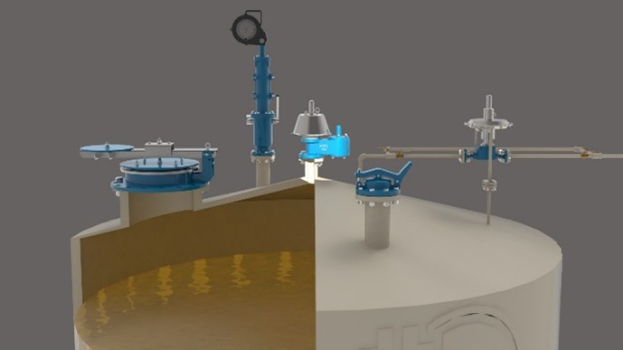
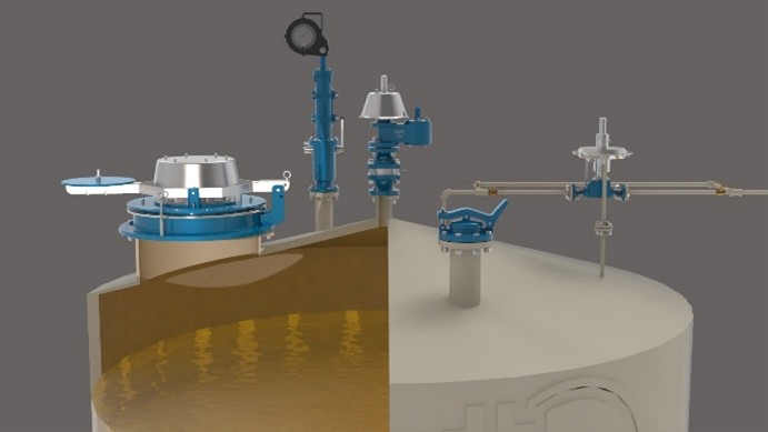
Gas Blanketing or Tank Padding System with: Gas Blanketing Valve (BGR), Pressure Vacuum Relief Valve (PVRV) with or without Flame Arrester, and Emergency Relief Hatch (ERV) or Emergency Vent.
6. Gas Blanketing Valve (BGR)
The BGR valve controls nitrogen admission into the tank.
When pressure decreases:
the valve opens
nitrogen is introduced
positive pressure is restored
When pressure increases:
the valve closes
The gas blanketing valve should not be considered as a tank pressure or vacuum relief device. Its main function is to maintain the inert atmosphere and compensate for normal pressure variations during operation.
In direct-acting blanketing valves, the valve operates around a single set pressure. The valve opens when tank pressure falls below that value and closes again when pressure recovers to the set pressure or slightly above it.
As tank pressure progressively decreases below the set point, the valve increases inert gas flow into the tank. Similarly, as pressure recovers, the valve gradually reduces flow until closing again.
6.1 Basic Sizing Criteria for Blanketing Valves
Blanketing valve sizing typically considers the maximum inert gas demand associated with tank emptying and thermal effects, including atmospheric cooling, vapor condensation, and thermal contraction.
In these types of valves, critical specification data typically includes: body size, connections, pressure supply, outlet pressure range or setting pressure, maximum back pressure, materials of construction, seal materials, temperature limits, and remote or integral sensing option.
6.2 KSPC Blanketing Valves
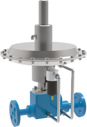
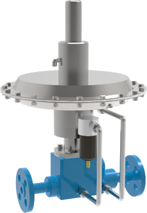
DST-50
Application for small and medium capacities.
Characteristics:
Sizes: ½” to 1”
Materials: SS304 / SS316
Capacity:
o 10–55 Nm³/h of nitrogen
DST-100 / DST-200
Application for larger capacities.
Characteristics:
DST-100
Sizes: ½” to 1”
Materials: SS304 / SS316
Capacity: 179–1060 Nm³/h
DST-200
Sizes: 1½” to 2”
Materials: SS304 / SS316
Capacity: 265–2760 Nm³/h
6.3 Importance of the Pilot Sensing Line
In low-pressure blanketing systems, it is highly recommended to use blanketing valves equipped with a pilot sensing line.
In very low-pressure systems, the pilot sensing line is essential for the valve to detect the actual pressure inside the tank vapor space.
If the valve attempts to sense pressure through the same line used to inject nitrogen, significant control errors may occur because nitrogen supply pressure may be much higher than the actual tank pressure.
The sensing line connection should be located sufficiently far from the nitrogen discharge point into the tank to avoid reading errors caused by turbulence or localized inert gas flow.
When the valve attempts to sense pressure using only the nitrogen injection line, the following may occur:
unnecessary overpressure
operational instability
premature PVRV opening
excessive nitrogen losses
system oscillations
increased inert gas consumption
This aspect is particularly important in very low-pressure systems, where small pressure variations may significantly affect tank operational stability.
7. Pressure Vacuum Relief Valve (PVRV)
PVRVs are the primary operational protection devices for atmospheric tanks.
These valves protect against:
overpressure
vacuum
operational tank breathing
vapor thermal expansion
vapor thermal contraction
rapid tank emptying
In API 2000 terminology:
Thermal outbreathing: thermal expansion of vapors caused by temperature increase.
Thermal inbreathing: thermal contraction of vapors caused by temperature decrease.
PVRVs are also commonly known in API 2000 atmospheric tank applications as:
conservation vents
breather valves
pressure-vacuum vents
These valves allow the tank to “breathe” in a controlled manner to prevent rupture due to overpressure or collapse due to vacuum.
PVRVs are also important emission control devices because they help reduce evaporative losses and VOC emissions.
In addition to normal venting requirements caused by tank filling and thermal vapor expansion, the pressure side of the PVRV may also act as operational protection during abnormal blanketing conditions such as a failed-open BGR valve.
In very low-pressure atmospheric applications, many PVRVs use weight-loaded pallets instead of springs due to the extremely low required set pressures.
Without a proper vacuum relief system, an atmospheric tank may collapse or implode during emptying operations or severe thermal changes.
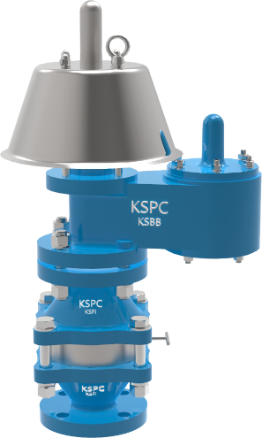
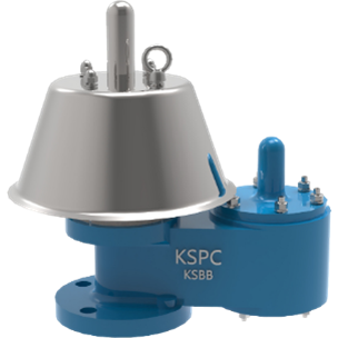
KSPC KSBB/KSBS and KSBG/KSGS valves are designed according to API 2000 for atmospheric and low-pressure applications.
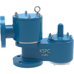
7.1 KSPC PVRV Types
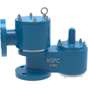
KSBB / KSBS – Vent to Atmosphere
Designed for direct atmospheric discharge.
Characteristics:
pressure and vacuum protection
prevention of evaporative losses
prevention of air ingress
available in aluminum, carbon steel and stainless steel
KSBG / KSGS – Pipe Away Venting
Designed to route vapors to closed systems or vapor recovery systems.
Typical applications:
vapor recovery
environmental control
toxic vapors
closed systems
8. PVRV Opening Philosophy
In many API 2000 atmospheric valve designs, PVRVs may begin opening at approximately 75% to 80% of the set pressure, depending on the manufacturer and valve design.
This applies to both:
pressure relief
vacuum relief
8.1 Coordination Between BGR and Pressure PVRV
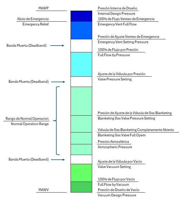
The BGR valve must fully close before the PVRV begins to open.
Therefore, the 75%–80% opening point of the PVRV should remain sufficiently above the BGR operating set point to avoid unnecessary nitrogen losses.
This pressure margin between devices is commonly known as the operational deadband.
A proper deadband allows each device to operate within its intended range without interfering with the next protection device.
When deadbands are insufficient, the following may occur:
unnecessary nitrogen losses
premature PVRV opening
unnecessary ERV activation
pressure oscillations
vibration and premature seal wear
significant increase in nitrogen consumption
Repeated and unstable vents operation may cause continuous opening and closing of pallets and covers, leading to accelerated seal wear, seat damage, increased fugitive emissions, difficulty maintaining blanketing stability and significantly higher nitrogen consumption.
A wider normal operating range between the BGR operating set point and the initial PVRV opening point helps reduce:
unnecessary nitrogen losses
continuous vapor venting
VOC emissions
evaporative product losses
Additionally, a stable operating range generally results in reduced valve cycling frequency, improved pressure stability and lower equipment wear.
The correct operational sequence should be:
The BGR introduces nitrogen
The BGR fully closes
Tank pressure continues increasing
Only then does the PVRV begin to open
The failed-open condition of the gas blanketing valve (BGR) should be considered a credible abnormal condition during system evaluation.
Preferably, this additional flow should be handled by the pressure side of the PVRV so that the ERV remains reserved for severe emergency conditions such as external fire exposure or rapid vapor generation.
Allowing the ERV to operate regularly due to a failed-open BGR condition is not considered good operational philosophy because it may cause unnecessary emergency vent activation, premature seal wear and operational instability.
Nevertheless, total system capacity must be verified to ensure that even under this abnormal condition the internal tank pressure does not exceed the MAWP.
Figure – Operational Hierarchy and Pressure Coordination in a Blanketing Gas System

8.2 Vacuum Protection
When the tank enters vacuum:
The BGR attempts to introduce nitrogen
Internal pressure begins recovering
The vacuum PVRV begins opening only in case of failure or insufficiency of the blanketing system
In a properly designed system, the vacuum PVRV should normally remain closed and act only as a backup protection device.
To avoid unnecessary atmospheric air ingress, sufficient margin should exist between the BGR operating set point and the initial opening point of the vacuum side of the PVRV.
⚠ Typical conditions that may activate the vacuum PVRV:
BGR valve failure
insufficient nitrogen supply
control system failure
extremely rapid tank emptying
abnormal operating condition
8.3 Actual Function of the Vacuum PVRV
The primary function of the vacuum PVRV is to mechanically protect the tank during abnormal conditions or blanketing system failure by preventing internal vacuum from exceeding the MAWV (Maximum Allowable Working Vacuum), thereby avoiding:
roof collapse
shell deformation
severe structural damage
8.4 Proper Design Philosophy
The correct philosophy is for the BGR to completely handle normal tank breathing while the vacuum side of the PVRV remains normally closed and acts only as backup protection during abnormal or failure conditions.
The vacuum side of the PVRV normally begins to open at approximately 75%–80% of its vacuum setting.The correct philosophy is that:
9. Emergency Relief Devices (ERV)
9.1 ERV Operational Philosophy
The ERV should remain closed during normal tank operation and operate only during true emergency conditions such as external fire exposure or massive vapor generation.
9.2 Initial ERV Opening
Like PVRVs, ERVs normally begin opening at approximately 75% to 80% of their set pressure.
This means the ERV may begin lifting before reaching its nominal set pressure.
9.3 Coordination Between the PVRV and the ERV
The PVRV must completely handle normal tank operating conditions.
Therefore, the PVRV must achieve full flow before reaching 75–80% of the ERV set pressure, and sufficient pressure margin must exist between both points to prevent:
premature ERV opening
unnecessary venting
vibration
operational instability
premature ERV wear
premature seal and pallet deterioration
9.4 Types of Emergency Relief Devices
Emergency relief devices used in API 650 atmospheric tanks may be found in different configurations, including:
emergency vents
emergency relief valves
emergency relief hatches (ERV)
Although these terms are often used generically to describe the tank emergency relief system, constructive and functional differences exist between them.
9.4.1 Emergency Vent
This is the general term used to describe any device designed to relieve large flow rates during emergency conditions, mainly:
external fire
severe overpressure
rapid vapor generation
9.4.2 Emergency Relief Valve
In some cases, emergency relief may be provided using calibrated mechanical valves employing pallets, discs or weighted covers.
However, in large API 650 atmospheric tanks, large-diameter emergency hatches or vents are more commonly used.
9.4.3 Emergency Relief Hatch (ERV)
The emergency relief hatch is a specific type of emergency vent, normally large diameter and high-capacity, which lifts during emergencies to rapidly relieve large vapor volumes.
It generally consists of:
hinged cover
counterweighted cover
swing cover
Emergency relief hatches are very common in:
API 650 atmospheric tanks
large diameter tanks
applications requiring high external fire relief capacities
9.5 MAWP and Emergency Relief
Although coordination between devices is critical, the final requirement remains that the ERV must discharge the required emergency flow while maintaining tank pressure below the MAWP, that is, below the maximum tank design pressure.
9.6 Tanks with and without Frangible Roof-to-Shell Joint
In API 650 tanks, two main philosophies exist for handling severe overpressure caused by external fire:
Tanks with weak roof-to-shell joints
Tanks without weak joints equipped with ERVs or emergency relief hatches
9.6.1 Tanks with Frangible Roof-to-Shell Joint
In tanks with frangible roof-to-shell joints, the roof-to-shell connection is designed to fail in a controlled manner before major structural tank failure occurs.
During an external fire:
vapor generation rapidly increases
internal pressure increases
the roof-to-shell joint partially separates
excess gases are released
This philosophy is accepted by API 650 for certain atmospheric tank configurations. However, the frangible roof-to-shell joint should not be considered an operational pressure relief device, but rather a structural tank protection mechanism for extreme conditions.
9.6.2 Tanks without Frangible Roof-to-Shell Joint
When the tank does not have a frangible joint, installation of the following is normally required to handle the emergency relief flow:
emergency vents
emergency relief valves
emergency relief hatches (ERV)
In these cases, the ERV constitutes the primary protection system against severe overpressure.
9.7 Practical Recommendation
Personally, I recommend the use of emergency relief hatches or emergency vents even in tanks equipped with frangible roof-to-shell joints, in order to minimize or avoid failure of the roof-to-shell joint.
Although the frangible joint protects the tank against catastrophic failure, its activation normally implies:
taking the tank out of service
performing structural repairs
additional inspections
possible operational losses
increased maintenance costs
Conversely, a properly sized ERV can relieve emergency overpressure without causing permanent structural damage to the tank.
10. KSPC Emergency Relief Vents
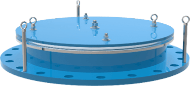
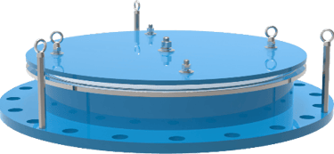
KSEP – Emergency Relief Valve
Designed for emergency relief in atmospheric tanks.
Characteristics:
API 2000 compliance
external fire protection
sizes DN400–DN750 (16”–24”)
set pressures: 50–700 mm H₂O
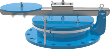
KSEPK – Hinged Emergency Relief Valve
Hinged or swing-type version.
Advantages:
easy inspection
quick tank access
high relief capacity
widely used in large API 650 tanks
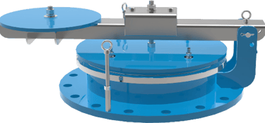
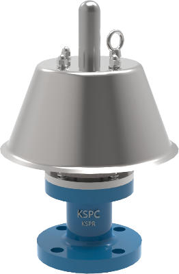
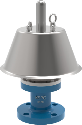
KSEPR / KSEPS – Emergency Relief Valve
Compact emergency vent configurations.
Characteristics:
set pressures:
o KSEPR: 20–700 mm H₂O
o KSEPS: 700–9000 mm H₂O
multiple material options
API 2000 applications
11. Flame Arresters
In some systems, the PVRV incorporates a flame arrester. Typical configuration include:
PVRV Atmospheric Discharge with Flame Arrester
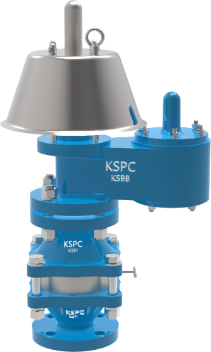
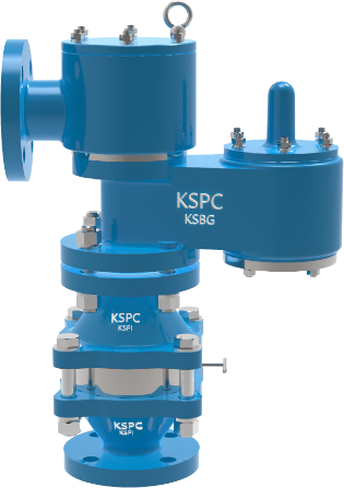
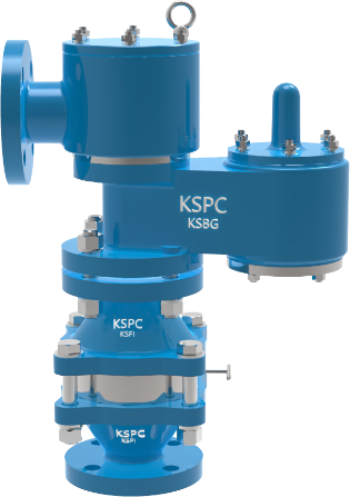
PVRV Discharge to Pipeline with Flame Arrester
The flame arrester prevents flame propagation from the outside atmosphere into the tank interior.
This is common in:
fuels
solvents
flammable hydrocarbons
However, flame arresters introduce:
pressure loss
flow restriction
maintenance requirements
potential fouling
The pressure drop introduced by the flame arrester must be considered during sizing of the PVRV and the venting system, since it may affect the effective relieving capacity and the operating pressures of the system.
Additionally, insufficient maintenance or fouling within the flame arrester may significantly reduce venting capacity and negatively affect the overall performance of the system.
For this reason, in addition to the proper selection of relief devices, it is essential to understand how valves develop their flow capacity and how overpressure directly influences the maximum pressures experienced by the tank.
12. What Does Overpressure Mean?
Relief valves normally do not achieve full flow exactly at set pressure. To handle the required flow rate, system pressure must increase above the set pressure.
This additional pressure increase is commonly referred to as:
overpressure
accumulation
In general terms, both concepts represent the pressure increase required for the valve to achieve full relieving capacity.
The lower the allowable overpressure:
the larger the valve size required
the lower the maximum required tank pressure
Conversely, allowing higher overpressure makes it possible to use smaller valves, but requires a more robust tank design.
Important Note
The values shown in the following examples are illustrative and intended to explain the coordination philosophy between the BGR, PVRV and ERV.
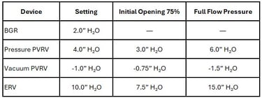
Actual opening pressures, accumulation and relieving capacities must be verified using manufacturer capacity curves and the specific criteria applicable to the required flow rate and actual operating conditions.
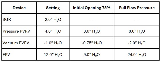
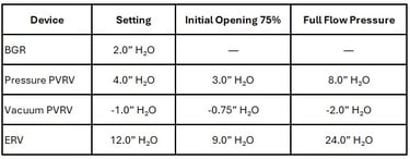
In many large-capacity API 2000 atmospheric valves, particularly weight-loaded pallet valves, approximately 100% overpressure may be required to achieve full opening and maximum relieving capacity.
12.1 Comparative Overpressure Examples
Common Assumptions
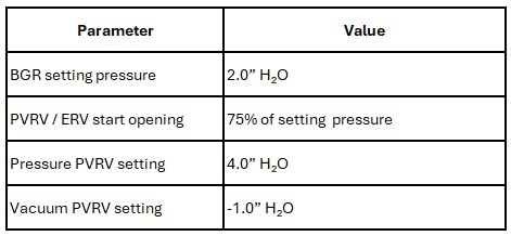
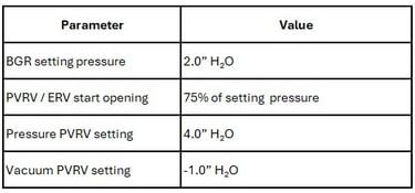
The BGR begins to open when tank pressure falls below its set pressure and progressively reduces flow as pressure recovers.
In these examples, the BGR is considered to operate around a single operating set point and not as a vacuum relief device.
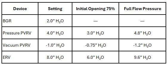
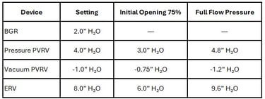
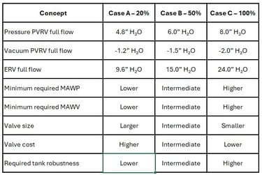
12.1.1 Case A – PVRV and ERV with 20% Overpressure
This case represents a design philosophy where maintaining low maximum tank pressures is prioritized by using larger valves to limit the required overpressure.
12.1.2 Case B – PVRV and ERV with 50% Overpressure
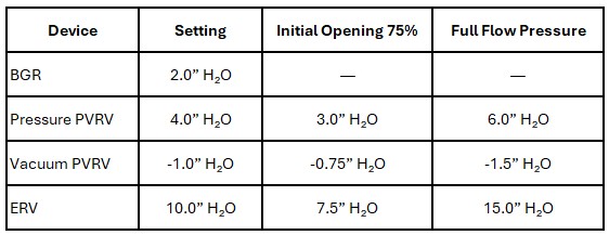
This case represents an intermediate solution between structural robustness and valve sizing.
12.1.3 Case C – PVRV and ERV with 100% Overpressure
This case represents a philosophy where higher overpressure is allowed to reduce valve size, requiring a more robust tank.
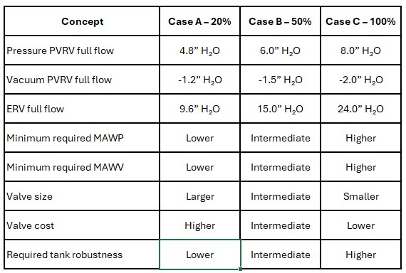
12.1.4 Comparative Table
12.1.5 Design Considerations
When valves capable of handling the required flow with lower overpressure percentages are selected, for example 20%, the maximum pressure reached inside the tank will be lower.
This allows operation with lower required values of:
MAWP
MAWV
roof lifting pressure
structural stresses
However, achieving the same flow rate with lower overpressure normally requires:
larger effective flow area
larger valve sizes
higher venting capacity
This increases the cost of:
PVRV valves
emergency vents
flame arresters
nozzles and connections
Conversely, when higher overpressure is allowed, for example 100%, the valve may be smaller and less expensive, but the tank must be capable of withstanding significantly higher pressure and vacuum conditions.
This may require:
more robust roofs
higher design pressure
higher vacuum resistance
additional structural reinforcements
higher roof lifting pressure
For this reason, final selection normally represents a technical-economic balance between:
valve cost
tank structural cost
required mechanical robustness
operational philosophy
API 650 and API 2000 requirements
maintenance and operational reliability
13. Conclusions
Designing a gas blanketing system requires much more than selecting individual valves.
Careful coordination is required between:
MAWP
MAWV
BGR
PVRV
ERV
set pressures
overpressure
flow capacities
pressure margins between devices
Poor coordination may result in:
continuous nitrogen losses
unnecessary air ingress
premature vent opening
excessive VOC emissions
operational instability
structural tank damage
A correct design philosophy allows:
maximum safety
reduced emissions
lower nitrogen consumption
longer device service life
stable and reliable operation
KSPC DST, KSBB, KSBG, KSEP, KSEPK and KSEPR valves provide solutions for blanketing, operational relief and emergency relief applications in atmospheric and low-pressure tanks in accordance with API 2000.
Gas blanketing systems are normally used in fixed roof tanks storing volatile or flammable products and, in some cases, tanks equipped with internal floating roofs (IFR), depending on roof configuration, vapor space arrangement and specific operating requirements.
A properly coordinated gas blanketing and venting system improves operational stability, reduces emissions and nitrogen losses, minimizes maintenance requirements, and enhances the overall mechanical integrity and safety of the tank.
Details
engineering
info@aceinteca.com
© 2024. All rights reserved.
Technical Information for Tank Equipment Courtesy of World Bridge Industrial Co. Ltd.
Technical Information for Tanks Protection Devices Courtesy of Korea Steel Power Corp.
Technical Information for Bolted Tanks Courtesy of Center Enamel.
Glass Fused Steel Bolted Tanks
Stainless Steel Bolted Bolted Tanks
Aluminum Suspended Deck for Cryogenic Tanks.
Aluminum Rolling Ladder for External Floating Roofs
WhatsApp +58 416 6289796