API STD 650 Vertical Tank Accessories Nozzles
Ing. José Félix Acevedo B.
9/21/202510 min read
1. Introduction:
Atmospheric and low-pressure storage tanks require a variety of mechanical and structural accessories to ensure their operation is safe, efficient, and in accordance with applicable technical standards. These accessories not only allow the tank to be connected to the process lines, but also facilitate inspection, maintenance, fire protection and operational access.
This document is part of a specialized technical series that addresses the main groups of tank accessories, including:0
Shell and roof connections: Nozzles for product inlet/outlet, venting, cleaning, instruments, sampling, and mixers (current document).
Accesses and structures: Helical or vertical stairs, platforms, railings and skirting boards.
Fire protection: Foam systems and cooling water system.
Additional requirements for floating roofs: Primary and secondary seals, vents, articulated or flexible drains, and anti-rotation devices, legs or support columns.
2. Shell and roof nozzles
The nozzles installed on the shell (body or wall) and on the roof of vertical storage tanks are fundamental elements for the operation, maintenance and monitoring of this equipment. They are generally manufactured from pipes, plates, flanges, and other fittings, selected according to the function of the nozzle, the type of service, and the requirements of the project.
The most common configurations are:
Slip-On (SO) or Welding Neck (WN) type flanges for nozzles with a diameter equal to or greater than 3".
Socket Weld (SW) flanges for nozzles with a diameter of less than or equal to 2".
Lap Joint (LJ) flanges in applications where precise alignment or use of different materials between neck and flange is required.
Threaded couplings (NPT) or SW type welded couplings for instrument connections and auxiliary services.
Quick connections for hoses in services that require frequent disassembly or operational flexibility.
Flanges can have either a raised face (RF) or a flat face (FF), and their pressure class is usually defined by class 150#, 300#, or others, as set in the project's piping class.
These nozzles fulfill essential functions such as:
Product inlet and outlet.
Recirculation and internal mixing.
Bottom drain and cleaning.
Level connections, temperature, pressure and alarm instruments.
Manual measurement, gauging and sampling.
The different types of nozzles and accessories will be addressed in a general way in the following sections, based on the indications of the API STD 650 standard, as well as on recommended practices by global operators and manufacturers, considering:
Nozzle function.
Typical sizes per service.
Recommended location.
Design and installation considerations.
2.1 Shell nozzles
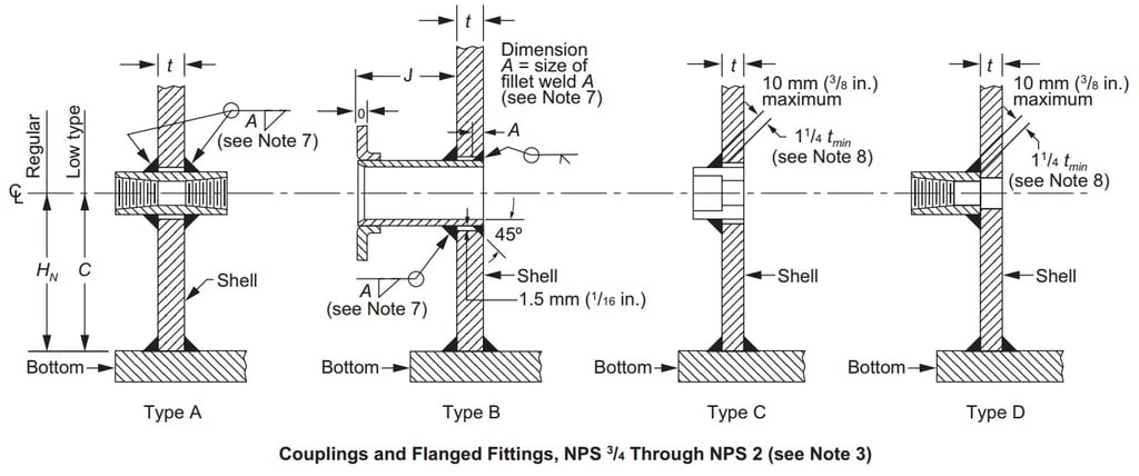
For the shell nozzles in API STD 650, flanged nozzles from 3/4" to 60" and with threaded couplings or Socked Weld from 3/4" to 3" are considered.
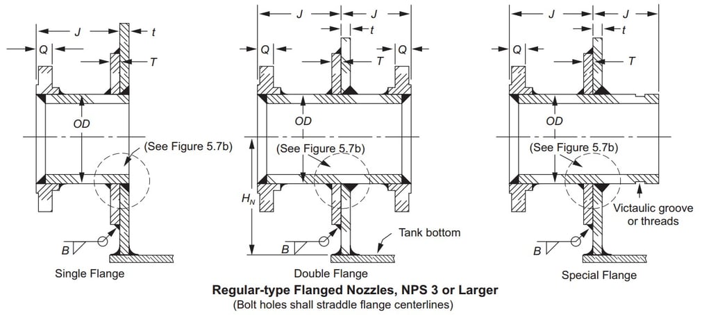
They can be:
Single flange flush with the inner shell of the tank or with a small internal projection.
Double flange, with internal flange for connection with some internal device such as floating suction, mixers etc.
Simple flange with internal projection to install vortex breakers or welded internal pipes.
2.1.1 Inlet nozzles.
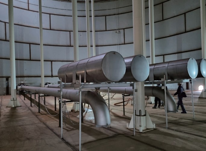
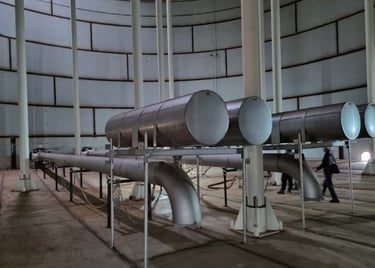
They can be installed on top of the shell and have vertical pipes.
They can be installed on the first ring of the shell.
To prevent static charge generation, a diffuser can be installed to reduce the output velocity to 3 feet per second (1 m/s).
In the case of tanks with floating roofs, diffusers may also be required to provide protection of the internal components.
2.1.2 Recirculation.
They are similar to inlet nozzles and are used for recirculation of the process product or to mix and/or homogenize the product.
When it is necessary to homogenize the product and reduce the formation of sediments, pipes with mixers can be installed.
Mixers can be:
Rotary (rotary Jet Mixer) installed in internal pipes.
Static (Jet Mixer) manufactured with concentric reductions, or with nozzles from specialized manufacturers.
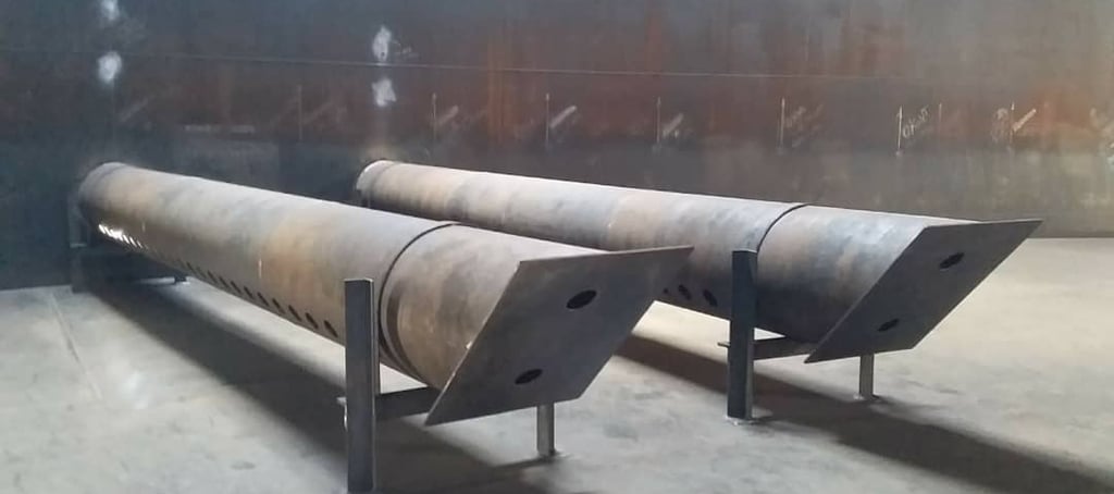
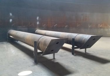
2.1.3 Outlet or suction nozzles.
They can be flush with the shell or have internal projection for the installation of a vortex breaker.
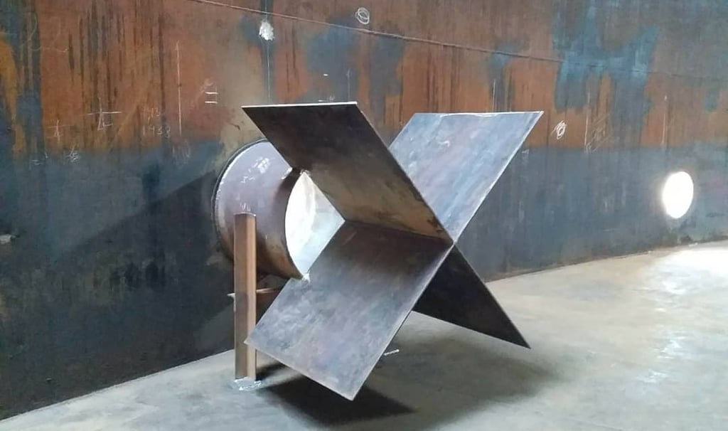
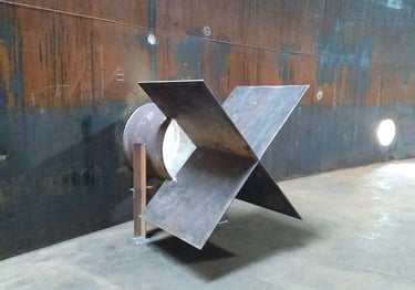
Vortex breakers are used to prevent eddies and the formation of air bubbles at the exit of the tank, they can be:
A single plate in an axial direction.
Cross plates (two plates in axial direction).
90º elbow with horizontal plate usually used in fire water tanks.
Internal Diffuser
They can be connected to floating suction lines, which incorporate rotary elbows and vortex plates, allowing product to be extracted from the top layer of the liquid, as is commonly required in aviation fuel applications.
Cross Plate Vortex Breaker
In certain applications they may be connected to skimmers used to recover the surface layer of crude oil or fuel that remains floating on the stored product.
Suction nozzles can also be flush-type connections.
API STD 650 indicates that these can be 8", 12", 16", 18", 20" and 24"
2.1.4 Overflow.
It is used to control the maximum liquid level of the tank.
In floating roof tanks, the overflow can be carried out through slots located in the upper part of the shell. This aspect will be discussed in more detail in the article on Additional Requirements for Floating Roofs.
In fixed-roof tanks it is a nozzle with a downer pipe installed inside or outside the tank. This pipe usually discharges the product into a tank.
In some cases, it may be considered to connect the overflow pipe to the bottom drain pipe when they are in the same orientation as the drain nozzle.
In some designs the overflow may have:
Box or pan for product collection.
Pipe reduction and vortex Breaker Plate.
NFPA 22 recommends the following in fire water tanks:
The overflow of water storage tanks for fire systems must be sized to handle the maximum filling flow.
If this value is unknown, the diameter of the overflow pipe must be at least one nominal measurement greater than that of the filling line. In addition, it must be equipped with a concentric reduction type inlet or other equivalent device, whose diameter is at least 2 inches (50 mm) greater than that of the overflow pipe itself.
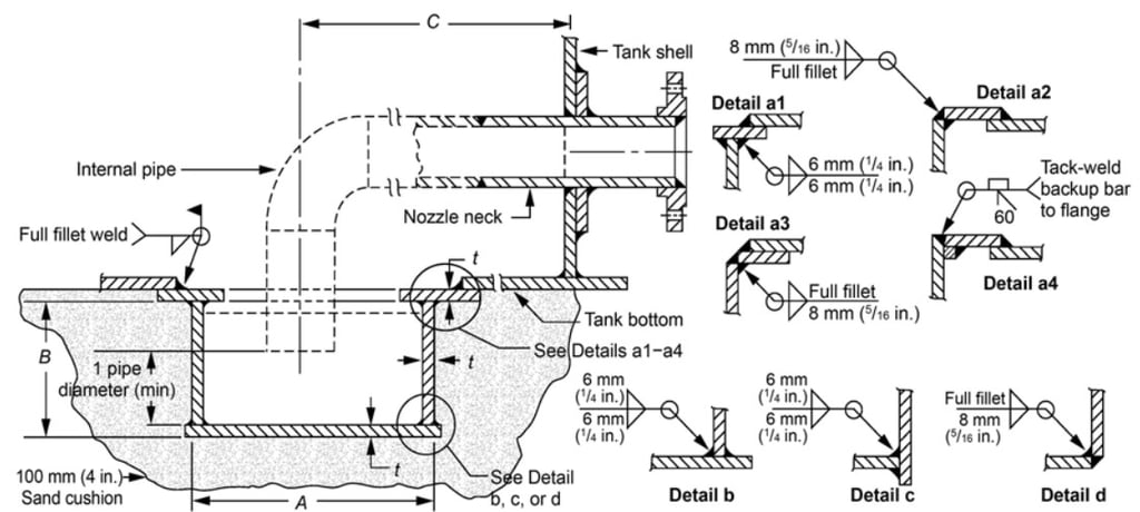
2.1.5 Drawoff Sumps.
They are flanged connections with internal projection, installed in the first shell ring used to perform tank drain or bottom water drain in hydrocarbon product storage tanks.
This connections can be 2", 3", 4" or 6" in diameter and has a sump that can be 610 mm, 910 mm, 1220 mm or 1520 mm (24", 36", 48" or 60") in diameter installed at the bottom of the tank and an internal pipe from the shell to the sump.
The quantity and size of the sump drains is normally specified by the customer in the data sheet
Floating Suction

Drawoff Sump
2.1.6 Samples Connections.
They are connections used to verify the quality of the product, depending on the process it may be required to take samples at different heights or simply to extract samples to verify the quality of the product.
They are small diameter connections, with blocking valves. Depending on the specifications and piping class, they can be; flanged, or threaded couplings or socket weld coupling.
2.1.7 Instruments Nozzles.
Usually in small diameters.
Commonly used to install pressure gauges, pressure transmitters and temperature indicators or transmitters (thermowells and thermocouples).
The size of the connections depends on the instrument to be installed and is usually specified by the customer in their data sheet.
2.1.8 Nozzles for thermal relief.
They are small diameter, threaded or 3000# Socket Weld type connections.
They are installed near the product inlet and outlet nozzles or in the neck of these nozzles and their function is to relieve the pressure in the pipe due to thermal effects when the product inlet or outlet blocking valve is closed.
2.1.9 Access.
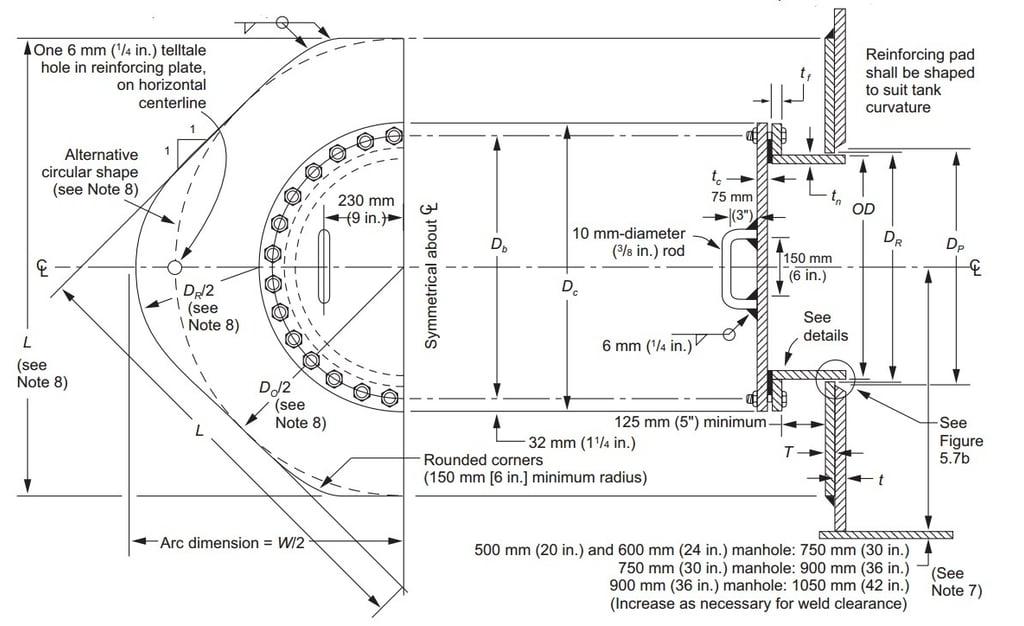
Manhole or access hatch.
They are used for access to the tank and to introduce materials into the tank in case of maintenance.
According to API STD 650 they can be 500 mm, 600 mm, 750 mm and 900 mm (20", 24", 30" and 36").
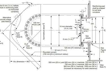
Manhole or Shell Hatch
They are made up of a neck, flange, cover and reinforcement plate. The neck can be made of pipe or rolled and welded plate. The reinforcement plate can be circular or diamond shape. The dimensions of the reinforcement plates, flange and cover shall be those indicated in the API STD 650 standard.
The cover has two handles for handling it.
Covers weighing more than 75 lb (34 kg) must be equipped with hinges or a davit that facilitates their safe opening and closing. The davit support arm should not be welded directly to the tank housing without an intermediate reinforcement plate that properly distributes the loads.
Manholes with diameters of 600 mm (24") and 750 mm (30") are the most commonly used in tanks, however, the number and diameter depends on the requirements of the plant or operator and should be installed whenever possible equidistant or diametrically opposed when even quantities are installed.
Rotary propeller mixers or agitators.
In case the process requires the use of rotary propeller or propeller mixers, these can be installed in nozzles with class 150# RF or FF flanges or in a manhole type connection, the size of the connection will depend on the size of the mixer or agitator specified.
Cleanout doors.
Flush-type cleaning doors are devices installed in the first ring of the tank shell, aligned flush with the bottom, allowing direct access to the interior of the tank for cleaning, sediment removal or major maintenance operations.
These doors are especially recommended in the following cases:
Severe service tanks, where products with high sediment content are stored, such as heavy crude oil, pitch, wax, fuel oils, or decantable residues.
Large diameter tanks, where interior access requires greater space and ease of maneuvering.
Tanks with periodic scheduled cleaning, where direct and unobstructed access to the bottom is needed.
Cases where internal obstructions are to be minimized, allowing the use of pressure cleaning tools, suction or machinery.
According to API STD 650 – Section 5.7.7, the standard nominal dimensions are:
203 mm × 406 mm (8” × 16”)
610 mm × 610 mm (24” × 24”)
914 mm × 1219 mm (36” × 48”)
1219 mm × 1219 mm (48” × 48”
They are manufactured entirely in the workshop and include:
Bottom reinforcement plate.
Plate for neck manufacturing.
Shell plate.
Shell reinforcement plate.
Fixing flange and Cover.
They require mandatory post-weld heat treatment (PWHT) to relieve residual stresses in the areas affected by the weld
The installation of davit is recommended for the cleanout door cover.
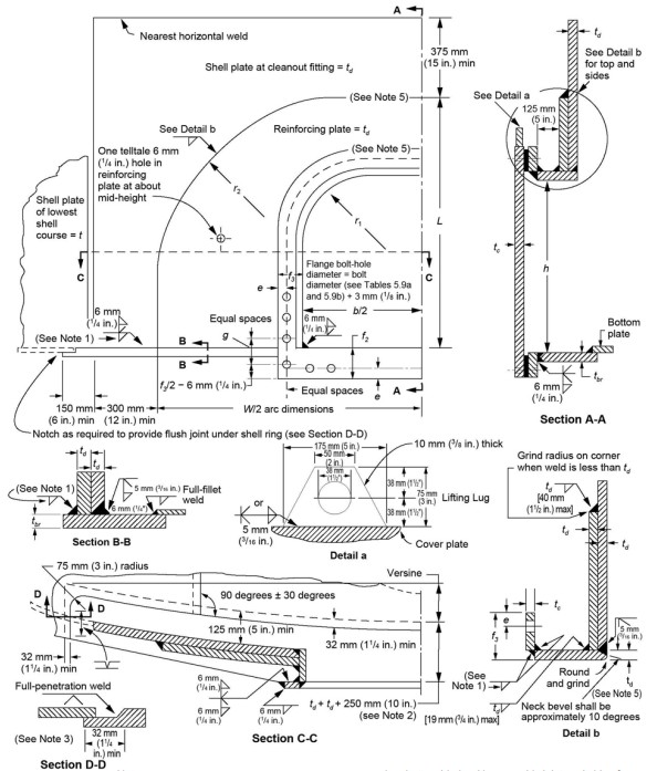
Flush-type Cleanout Door
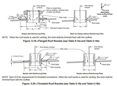
2.2 Roof Nozzles.
For the roof nozzles in the API STD 650, flanged nozzles from 1 1/2' to 12" and with threaded couplings or Socked Weld from 3/4" to 12" are considered.
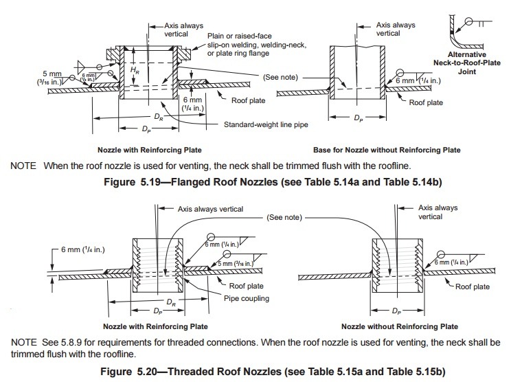
Roof Nozzles
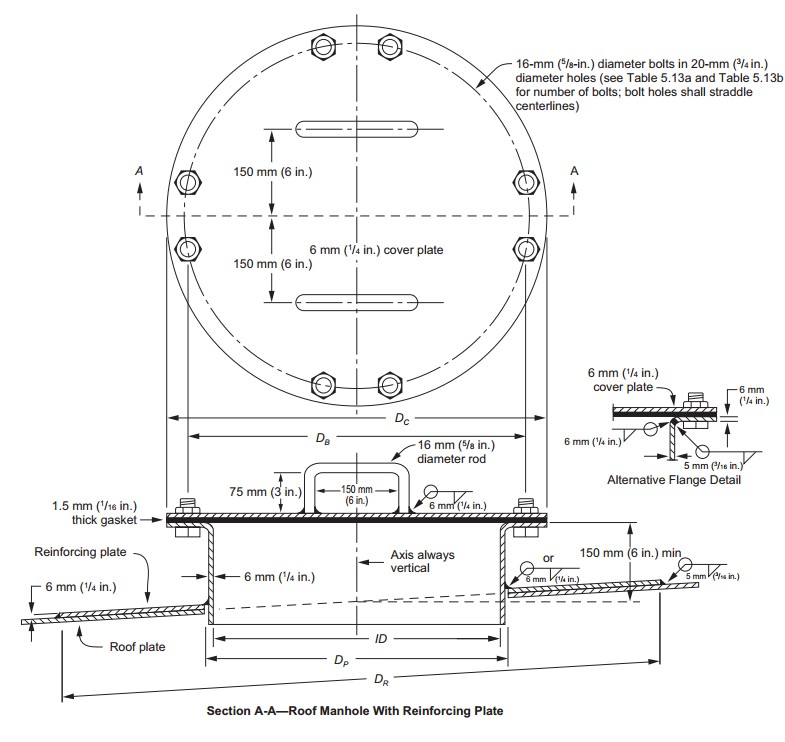
2.2.1 Manhole or access hatch.
Used for inspection, ventilation and lighting in case of maintenance.
According to API STD 650 they can be 500 mm, 600 mm (20" and 24"), although occasionally some customers request them in 750 mm (30"). The quantity and diameter depend on the requirements of the plant or operator and should be installed whenever possible equidistant or diametrically opposed when even quantities are installed.
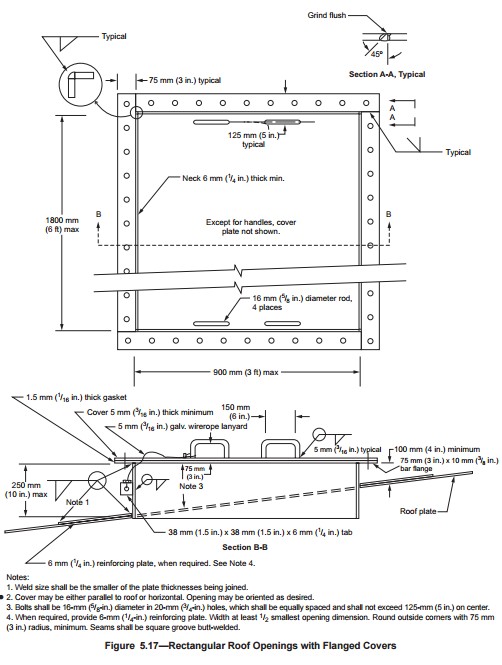
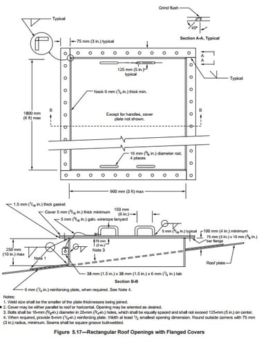
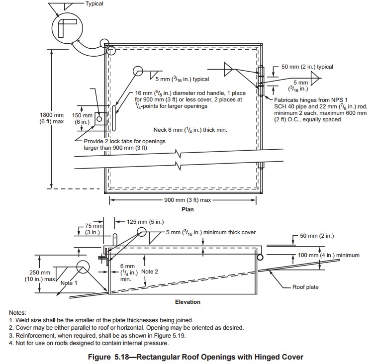
2.2.2 Rectangular Openings
Rectangular openings in the fixed steel roofs of vertical tanks are mainly used for access, inspection and ventilation. Its design must guarantee the structural integrity of the roof, considering possible external loads or operating conditions. In accordance with API STD 650 – Section 5.8.6, these openings must comply with the construction details shown in Figures 5.17 and 5.18:
Flanged covers (Fig. 5.17): They should not be installed in tanks where the internal pressure exceeds the self-weight of the roof plates.
Hinged covers (Fig. 5.18): Not to be used on roofs designed to contain internal pressure.
2.2.3 Instruments nozzles.
Vertical storage tanks, especially those used in the hydrocarbon and chemical industry, require the incorporation of specific nozzles on the roof for the installation of measuring and control instruments.
Instruments Commonly Installed on the Roof
Level transmitters: Used for continuous measurement of the product level inside the tank.
Temperature sonde: They allow you to monitor the temperature of the stored liquid, either at a single point or at multiple depths.
Level indicators and transmitters with floats.
Gauge hatches: Provide access for manual gauging, spot temperature measurement, or manual sampling.
These instruments usually require the installation of Stilling well Pipes
The accuracy of level and temperature instruments can be affected by liquid movements, foaming, or disturbances from product inlet/outlet. For this reason, it is common for these devices to be installed in conjunction with stilling wells pipes.
Typical dimensions of stilling well pipes:
Level Transmitters and Gauging Hatches: An 8" (DN200) diameter nominal stilling well pipe is recommended, although it may vary depending on the instrument manufacturer's specifications.
Temperature sondes: A 2" guide tube (DN50) is typically used, which allows the sensor assembly to be inserted without interference.
Important:
The dimensions and arrangement of the stilling well pipes must be checked against the technical requirements of the instrument to be installed, considering factors such as the type of sensor, mounting method, clearance required, and characteristics of the stored product.
2.2.4 Venting.
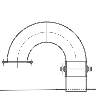
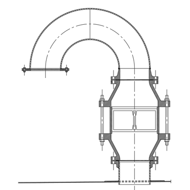
Free vents or open vents (with bird protection).
Generally used in tanks that store non-volatile products or in tanks with internal floating roofs, we can find vents with.
Gooseneck.
Chinese hat.
Gooseneck with flame arrester (used with volatile products).
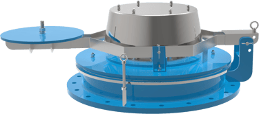
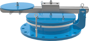
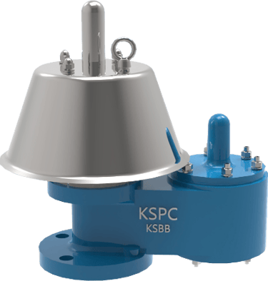
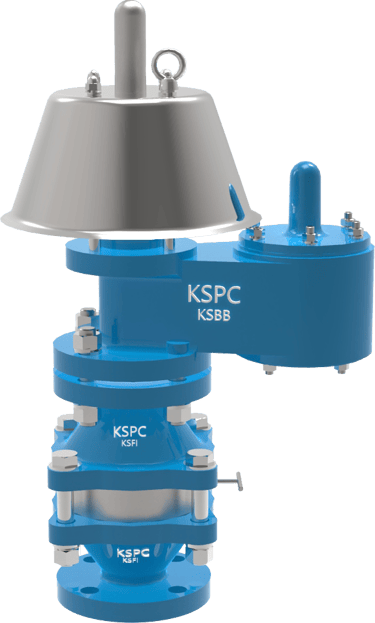
Pressure and vacuum vents.
Normally used in tanks with volatile products to reduce atmospheric emissions, we can achieve pressure vents with:
Pressure and vacuum valves with or without flame arrest.
Pressure relief valves.
Vacuum breaker valve with or without flame arrester.
Pressure and Vacuum Valves
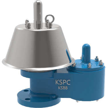
Emergency venting.
Normally used in tanks with volatile products that do not have a frangible joint in the roof-shell joint, these can be:
Pressure relief.
Pressure and vacuum relief.
Circulation Vents
Circulation vents are essential components in tanks with fixed roofs equipped with internal floating roofs, as they allow the displacement of air or vapors as the liquid level changes. We will deal with this aspect in more detail in the article Additional Requirements for Floating Roofs.
Emergency Vents

Gooseneck Vents
Stilling Well Pipes
Roof Manhole
Details
engineering
info@aceinteca.com
© 2024. All rights reserved.
Technical Information for Tank Equipment Courtesy of World Bridge Industrial Co. Ltd.
Technical Information for Tanks Protection Devices Courtesy of Korea Steel Power Corp.
Technical Information for Bolted Tanks Courtesy of Center Enamel.
Glass Fused Steel Bolted Tanks
Stainless Steel Bolted Bolted Tanks
Aluminum Suspended Deck for Cryogenic Tanks.
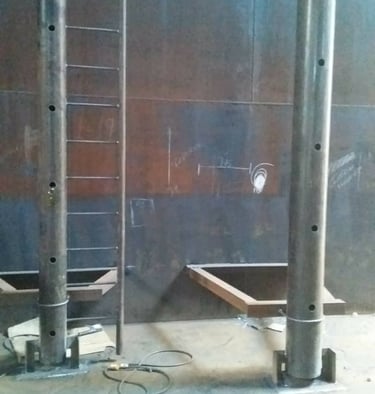
Aluminum Rolling Ladder for External Floating Roofs
WhatsApp +58 416 6289796