API 650 Vertical Tanks Accessories Anchor Bolts & Anchor Chairs
Ing. José Félix Acevedo B
10/5/20257 min read
1 Introduction
In storage tanks built under API Standard 650 – Welded Tanks for Oil Storage, the anchoring system is essential to guarantee structural stability against external loads such as wind, earthquake or internal pressure. This system is mainly composed of two elements:
Anchor bolts
Anchor chairs
Both elements work in an integrated manner to prevent the tank from lifting, sliding or overturning, in accordance with the requirements set forth in Section 5.12 of API 650 and its annexes
2 Anchor Bolts
2.1 What are they and what are they used for?
Anchor bolts are steel elements embedded in the concrete foundation, designed to link the tank to the foundation via anchor chairs. Its main function is to resist uplift forces (U) and transfer the overturning moments and tensile stresses generated by external loads, ensuring that the tank remains stable in the face of wind, earthquake or internal pressure conditions.
Anchor bolts are required when the tank—considering its own weight and that of the stored product— is not capable of withstanding lifting forces or overturning moments, which would make it structurally unstable under the following conditions:
Wind (Section 5.11.2): when pressure on the shell and suction on the roof generate overturning moments or uplift forces that exceed the total weight of the tank.
Seismic (Annex E): when seismic loads induce overturning moments that cause partial separation of the bottom from the foundation or compromise the overall stability of the tank.
Internal Pressure (Annex F): when the design internal pressure generates uplift forces that cannot be counteracted by the weight of the tank and the stored product.
In addition, API 650 considers combined loading conditions that may increase the effects of uplift and overturning, such as:
Wind + Internal Pressure, acting simultaneously and generating higher tensile stresses on the anchor bolts.
Seismic + Internal Pressure, combining the seismic overturning moment with the internal pressure force, reducing the effective resistance to overturning.
In these cases, the design of the anchor bolts must consider the most critical combined load condition, evaluating the capacity of the anchor bolts, anchor chairs, and foundation to resist the resulting stresses and ensure the overall stability of the tank.
In addition, anchor bolts may be required by purchaser's specification or local regulations, even when the structural analysis does not indicate instability, as an additional preventive safety measure.
2.2 Material Specifications for Anchor Bolts (per API 650 — Section 4.7 and 5.12)
Unless otherwise specified in the Tank Data Sheet, anchor bolts shall meet the following requirements:
Material:
o Round bar conforming to ASTM A36, threaded and galvanized, or
o Bolts conforming to ASTM F1554 Grade 36 or 55, galvanized.
Nuts: Galvanized heavy hexagonal.
Restrictions:
o Welding on galvanized bolts is not permitted.
o Bolts with a minimum yield strength greater than 55 ksi are not permitted.
Permissible stresses: According to Tables 5.20a and 5.20b of API 650.
Calculation: Based on the net thread root area or corroded diameter (the smallest).
Minimum corroded diameter: 25 mm (1 in).
Corrosion Allowance (CA): Defined by the buyer (usually not required in galvanized anchor design).
Retention system: Can include hooks or end plates to ensure effective anchoring.
2.3 Anchor Bolt Spacing, Quantity, and Diameter
According to API Standard 650 (2025), Sections 5.12.3, 5.12.6, and 5.12.7, the maximum spacing between adjacent anchor bolts shall not exceed 3 m (10 ft), measured along the outer circumference of the shell. This limitation ensures a uniform distribution of uplift and overturning forces around the tank perimeter and prevents localized stress concentrations on the shell and foundation.
The standard also requires a minimum of four (4) anchor bolts per tank, evenly spaced.
Based on the tank diameter (D) and the maximum allowable spacing, the minimum number of bolts can be estimated using the following expression:
Nmin ≥ [π D/3 m] o Nmin ≥ [π D/10 ft]
where Nmin is the minimum number of anchor bolts, rounded up to the next whole number to ensure a symmetrical layout around the shell.
The minimum corroded diameter of anchor bolts shall be 25 mm (1 in), as stated in API 650 section 5.12.6. The final diameter shall be determined by verifying that the tensile load per bolt (Fₐ), calculated under the most unfavorable load combination—wind (Section 5.11), seismic (Annex E), and internal pressure (Annex F)—does not exceed the allowable tensile stress defined in Tables 5.20a and 5.20b.
The design stress shall be based on the net root area of the thread or the corroded diameter, whichever is smaller.
A proper balance must be maintained between the number and diameter of anchor bolts:
Increasing the number of bolts reduces the load per bolt and minimizes local stress on the lower shell course.
Larger-diameter bolts, however, transmit higher loads to the shell and may require increasing the plate thickness of the first shell course to accommodate the induced stresses and prevent local distortion or shell buckling.
Although API 650 does not define a maximum diameter, in practice most design programs and manufacturer recommendations limit anchor bolt diameters to 3 inches (76 mm), and in special cases up to 4 inches (102 mm), depending on the anchor chair design, foundation configuration, and uplift loading.
Practical design approach:
Compute Nmin using the 3 m maximum spacing rule.
Evaluate uplift and overturning loads → determine tensile load per bolt (Fₐ).
Select a bolt diameter ≥ 1 in (25 mm) that satisfies allowable tensile stresses.
If not adequate, increase the number of bolts before enlarging the diameter, to avoid excessive local stresses on the lower shell course.
Select at the designer's discretion the best option for the number and diameter of anchor bolts.
2.4 Installation (5.12.12)
All anchor bolts shall be uniformly tightened to achieve a snug-tight condition, defined as the nut being in full contact with the top plate of the anchor chair, followed by a maximum additional rotation of one-eighth (1/8) turn using a wrench. This procedure ensures proper engagement of the threads without introducing excessive preload that could cause local deformation of the tank shell.
To prevent loosening of the nuts during operation, appropriate mechanical locking measures shall be applied, such as:
Peening of exposed threads, which consists of lightly hammering or deforming the thread ends to prevent the nut from rotating freely.
Use of locking nuts (double nuts or safety nuts).
Tack welding of the nut to the anchor chair.
These measures ensure the long-term integrity of the anchorage system, particularly under cyclic loading, vibration, or thermal expansion conditions.
2.5 Embedment length and design
The embedment length and anchorage design of anchor bolts within the concrete foundation are not defined by API Standard 650. These aspects are the responsibility of the civil or structural engineer in charge of the tank foundation design, who must consider parameters such as soil bearing capacity, concrete thickness and strength, reinforcement layout, and applicable anchorage design criteria.
Accordingly, the project specifications should clearly state that the embedment and retention design within the concrete—including the embedment length, anchorage type, and retention system (e.g., hooks or terminal plates)—shall be determined by the civil or structural engineer, ensuring proper interaction between the tank shell anchorage system and the supporting foundation.
3 Anchor Chairs
3.1 What are they and how do they work?
Anchor chairs are stiffened assemblies welded to the shell with a top plate designed to house the anchor bolt. Their functions are:
Distribute anchor bolt loads into the tank shell.
Prevent local stress concentrations that could damage the shell.
Allow shell deflection and rotation under external loads.
Accommodate thermal expansion, using slotted holes to absorb radial growth.
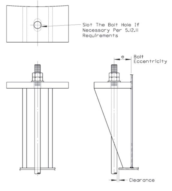
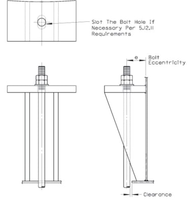
Anchor Chair
3.2 Design requirements (5.12.8–5.12.11)
The design of anchor chairs plays a key role in ensuring the structural stability of storage tanks built in accordance with API Standard 650, as these components are responsible for transferring uplift forces and overturning moments from the anchor bolts to the tank shell. For this reason, their geometry, stiffness, and connection details must comply with specific code requirements to ensure safe and reliable performance.
According to Section 5.12.7 of API 650, anchor bolts must be attached to the shell through stiffened chair-type assemblies or anchor rings of sufficient size and height to allow for installation, inspection, and corrosion protection. The height of the chair should be kept as low as practical to reduce local bending moments on the tank shell.
An accepted design procedure for anchor chairs is provided in AISI Steel Plate Engineering Data, Volume 2, Part 5 – “Anchor Bolt Chairs”, which defines typical proportions and design methods for these structural components. All parts of the chair (plates, stiffeners, welds, and top plate) shall be designed in accordance with AISC 360, using the Allowable Strength Design (ASD) method.
For wind or seismic loading, the allowable stresses may be increased by 33 %, provided that wind and seismic conditions are not combined in the same load case (Section 5.12.9).
Verification of local shell stresses shall be performed in accordance with Tables 5.20a and 5.20b of API 650, ensuring that the tensile and compressive stresses around the anchor attachments remain within the allowable limits (Section 5.12.10).
When a more detailed evaluation is required—such as for non-standard geometries or higher loads—an advanced analysis may be performed following ASME Section VIII, Division 2, Part 5, which allows local stress assessment using finite-element or equivalent analytical methods (Section 5.12.8).
In summary, anchor chairs must combine strength, rigidity, and maintainability, ensuring proper force transfer without compromising shell integrity.
A well-balanced design, supported by the references of AISI, AISC, and ASME, guarantees that the anchorage system meets the structural safety, durability, and reliability requirements established by API 650.
3.3 Location and Welding of Anchor Chairs (Section 5.8.1.2a)
According to API Standard 650 (2025), Section 5.8.1.2a, the edge of the weld bead attaching any permanent structural attachment — including anchor chairs, brackets, or other appurtenances — shall comply with the following minimum clearances from shell weld seams:
Not less than 150 mm (6 in.) from any vertical butt weld joint.
Not less than 75 mm (3 in.) from any horizontal butt weld joint.
Welds may cross butt joints only when they are continuous and oriented at an angle of at least 45° relative to the butt weld.
These spacing requirements prevent weld overlap, distortion, or stress concentration near primary shell joints, ensuring that structural attachments such as anchor chairs do not compromise the integrity of critical tank weld seams. Maintaining these clearances also facilitates nondestructive examination (NDE) and inspection of both the main shell welds and the attachment welds during fabrication and service.
4. Conclusions
Anchor bolts and anchor chairs together form an integrated structural safety system in tanks designed under API Standard 650:
Anchor bolts secure the tank to the foundation, preventing uplift or overturning.
Anchor chairs ensure that these loads are properly transferred to the tank shell, avoiding local overstress while allowing for thermal expansion and contraction.
The embedment design and anchorage into concrete are the responsibility of the foundation design engineer, while API 650 governs the minimum layout, allowable stresses, clearances from welds, and local shell stress verification.
In combination, these components are essential for tank stability under external loads such as wind, seismic, or internal pressure, and for maintaining the long-term reliability and structural integrity of welded storage tanks.
Details
engineering
info@aceinteca.com
© 2024. All rights reserved.
Technical Information for Tank Equipment Courtesy of World Bridge Industrial Co. Ltd.
Technical Information for Tanks Protection Devices Courtesy of Korea Steel Power Corp.
Technical Information for Bolted Tanks Courtesy of Center Enamel.
Glass Fused Steel Bolted Tanks
Stainless Steel Bolted Bolted Tanks
Aluminum Suspended Deck for Cryogenic Tanks.
Aluminum Rolling Ladder for External Floating Roofs
WhatsApp +58 416 6289796