API 650 Storage Tanks Levels & Capacities
Guide for Levels and Capacities Verification and Calculation
José Félix Acevedo B.
17 min read
1 Introduction
In storage tanks designed under API 650, the calculation of volumetric capacities depends on the diameter and height of the tank, as well as its operating levels. These levels, in turn, can be affected by external factors, such as:
Seismic wave height,
NPSH of the pumps,
Lifting of the outlet and overflow nozzles, among others.
This blog will explain how to calculate and verify the operating levels and consequently the different capacities of the tank, as well as the total height of the tank shell.
Important:
The designer must review the project specifications and ensure that the design meets all technical and regulatory requirements.
2 Definitions.
In the context of API 650 and API 2350 standards for storage tanks, it is critical to establish some key definitions.
2.1 General
2.1.1 Diameter (D)
It refers to the distance across the cross-section of the tank, i.e., the width of the tank in its widest section. Depending on the context, diameter can be defined in different ways:
Internal Diameter. The diameter is measured from the inside of the tank shell plates.
Nominal diameter. The diameter is measured to the axis of the tank shell plates.
Outer Diameter. The diameter is measured from the outside of the tank shell plates.
In this document, for calculation purposes, the diameter will be considered as the internal diameter of the tank
2.1.2 Total Shell Height (H)
The total height of the tank shell includes the top angle and is composed of rings made of vertically arranged of plates. These rings can be aligned in three ways:
Internally: Keeping the internal diameter constant.
To the axis of the plates: Keeping the nominal diameter constant.
Externally: Keeping the outer diameter constant.
Consideration in this document:
For the calculations showed here, it will be assumed that the shell plates are internally aligned.
2.1.3 Maximum Filling Rate (MFR)
It is the maximum flow rate with which the tank is filled. This can be indicated in m3/hr, m3/min or barrels/day (BPD)
2.1.4 Maximum Emptying Rate (MER)
It is the maximum flow rate with which the tank is emptied.
2.1.5 Cross Section Area (CSA)
It is the cross-sectional area of the tank and is calculated as the area of a circle [CSA = (π x D^2)/4].
2.1.6 Response Time (RT)
For calculation purposes in this document, it is assumed that the tank belongs to Category 3 according to API 2350, which implies that it has:
Automatic level measurement
Standalone sensors for HHLL and HLL alarms
Real-time remote monitoring.
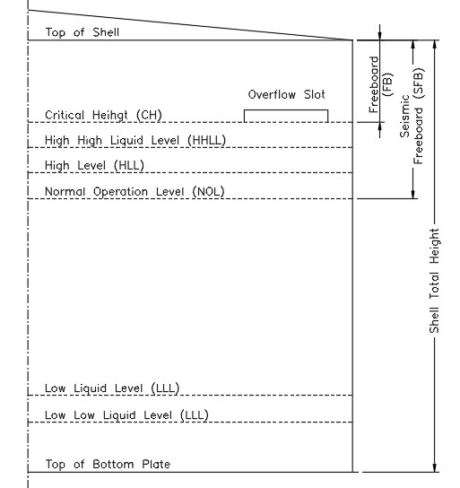
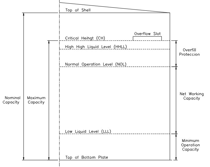
2.2 Levels (See Figure No. 1)
2.2.1 Low Low Liquid Level (LLLL)
The low low liquid level in a tank, is the operating limit that ensures safe operation. Its importance lies in the protection of equipment, avoiding damage to components such as pumps.
This level is set according to the process specifications and in many cases is related to the NPSH (Net Positive Suction Head) required by the pumps in the system. It also acts as a safety threshold, below which pumps should not operate in order to preserve their integrity and efficiency.
2.2.2 Low Liquid Level “LLL”
It is the minimum safe operation level of the tank. It depends on the response time required for emergencies, such as suction pump shutdown.
2.2.3 Normal Operation Level “NOL”
It is the highest working level to which the tank is routinely filled during normal operations.
2.2.4 High Liquid Level “HLL”
It is the level above the NOL that indicates that the normal level of operation has been exceeded. It can be used as an alarm to alert the operator to an abnormal product level condition.
2.2.5 High High Liquid Level “HHLL”
It is the maximum level of liquid that the tank can reach during normal operation.
2.2.6 Critical level (Critical Height “CH”)
Also known as critical height or liquid design level, it is the absolute maximum level that the product can achieve without causing overflows or structural damage to the tank. It is used for the structural calculation of the tank, specifically to determine the thicknesses of the shell plates.
2.2.7 Freeboard “FB”
It is the section of the tank shell that is above the critical level (CH). Its height depends on several factors: the location of the overflow slots or nozzles (if any), the location height of the foam chambers, the height of the floating roof (if installed), and the size of the fixed roof beams and/or clips.
2.2.8 Seismic Freeboard “SFB”
It is the additional height of the tank shell above the normal operating level (NOL), designed to contain the movement of the liquid induced by earthquakes (seismic wave).
Factors that influence its calculation:
Location and height of accessories, such as foam chambers.
Seismic wave height
Tank roof type:
o Fixed roof
o Floating roof
o Fixed roof with internal floating
The tank designer is responsible for calculating this height based on the applicable seismic regulations.
2.2.9 Overfill Protection
It is the height between the normal operating level (NOL) and the critical level (CH), which ensure a safety margin to avoid spillage and overfilling.
2.3 Capacities (see Figure No. 2)
Figure No. 1 Levels & Heights
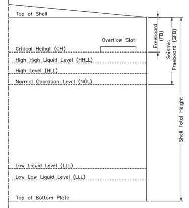
2.3.1 Nominal Capacity (NC)
It is the volume of the tank calculated with the product of the tank cross-sectional area and the total shell height (CN = CSA x H).
2.3.2 Maximum Capacity (MC)
It is volume resulting from the multiplication of the cross-sectional area of the tank and the critical level of the product (CM = CSA x CH).
2.3.3 Minimum Operating Capacity (MOC)
It is the volume below the low operating level (LLL) which cannot be pumped and is the result of the tank's cross-sectional area product and the low liquid level (MOC = CSA x LLL).
2.3.4 Net Work Capacity (NWC)
It is the volume of liquid between the normal operating level (NOL) and the low level (LLL) and is calculated by multiplying the cross-sectional area of the tank with the difference of levels indicated above [NWC = CSA x (NOL-LLL)].
2 Levels and Capacities Calculation.
Initial Data for Tank Design
When designing a tank, you receive the tank data sheet, which contains key information, including:
Tank Diameter
Total shell height
Maximum Liquid Design Level
Fill flow rate
Emptying flow rate
Nozzle List
Figure No. 2 Capacities
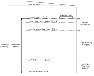
With this data, the nominal capacity and the maximum capacity of the tank can be determined initially.
Important:
The customer must clearly define the required base capacity (Nominal, Maximum or Net Working?), since the following levels and parameters of the tank will be calculated and verified from this capacity:
Minimum Level (LLLL)
Low Level (LLL)
Normal Operating Level (NOL)
High Level (HLL)
Critical Level or Critical Height (CH)
Seismic Wave Height (SWH)
Total height of tank shell (H)
After verifying these parameters, they must be validated with the customer, who will be informed if it is necessary to adjust the height of the tank shell to ensure compliance with the operational requirements and the API 650 and API 2350 Standards.
3.1 Levels and Heights
3.1.1 Low Low Liquid Level (LLLL)
The calculation of this level depends on several factors, such as:
Suction nozzle elevation·
Vortex Breaker Type
Below are the four (4) most common cases.
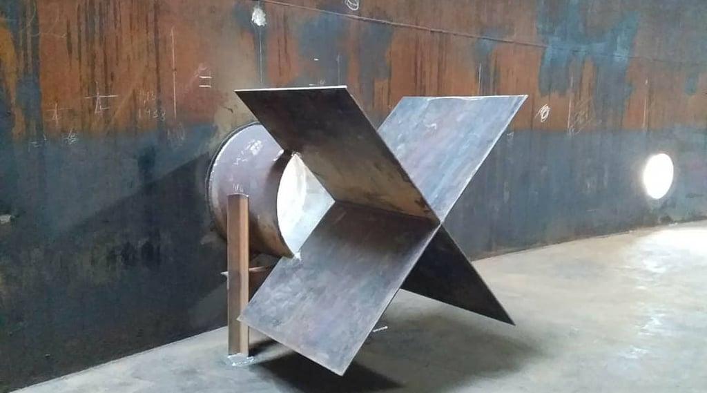
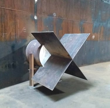
3.1.1.1 Case 1. Vortex breaker with cross plates (See Figure No. 3)
In this case, the minimum level (LLLL) depends on:
Nozzle height (hn)
Nominal nozzle diameter (d)
It is determined by the following equation:
LLLL = hn + d
The height or elevation of the suction nozzle can be specified in the tank data sheet. If not defined, the elevation indicated in API 650 Table 5.6b (column 8 or 9), which provides values for both regular and low type nozzles, can be used.
If Table 5.6b is not available, it can be assumed that the height of the nozzle is equal to its nominal diameter (d) plus 127 mm.
The distance "cl" is the clearance between the vortex breaker plate and the floating roof, while "dr" is the draft of the floating roof, determined by the tank designer. The floating roof height in the low position must be set considering the minimum level (LLLL), the floating roof draft (dr) and a clearance (cl) of at least 150 mm. The tank designer is responsible for determining the height of the floating roof in the low position by checking for all internal interference.
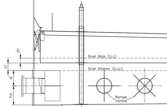
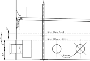
Figure No. 3
Cross Vortex Breaker Suction Nozzle.
3.1.1.2 Case 2. Vortex breaker with cross plates, alternative (See Figure No. 4)
This case is a variation of the previous one. The calculation of the minimum level (LLLL) depends on the nozzle elevation (hn), the nominal diameter (d) and a free distance (cl), according to the following equation:
LLLL = hn + cl + d/2
If the customer does not indicate otherwise:
For tanks without a floating roof, cl = 0 is assumed.
For tanks with a floating roof, a cl between 0 and 150 mm is recommended, according to the criteria of the floating roof designer.
The distance "dr" corresponds to the draft of the floating roof, i.e. the depth that the roof sinks into the liquid.
The tank designer should set the floating roof height to the low position, considering the LLLL, the ceiling draft (dr) and a minimum clearance (cl) of 150 mm, and any other internal interference
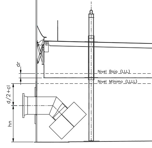
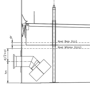
Figura No. 4
Cross Vortex Breaker Suction Nozzle (alternative)
3.1.1.3 Case 3. Vortex Breaker with Horizontal Plate (See Figure No. 5)
This case is common in suction nozzles of fire water tanks. The calculation of the minimum level (LLLL) depends on the height (h1) of the vortex breaking plate and the recommended free distance (cl), according to the following equation:
LLLL = h1 + cl.
To determine h1, the highest value between half the nominal nozzle diameter (d/2) and 150 mm must be taken.
Although NFPA 22 does not require a minimum clearance, it is recommended that the tank designer consider a value of "cl" between 50 and 305 mm, unless otherwise indicated by the customer.

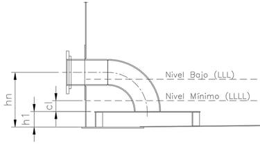
Figure No. 5
Suction Nozzle with Horizontal Vortex Breaker
3.1.1.4 Case 4. Flush bottom suction nozzle with vortex breaker (See Figure No. 6)
This case is rare; in more than 35 years of experience, I have only found it on one project. These are flush-bottom suction nozzles, in accordance with Figure 5-14 of API 650. This design applies to 8", 12", 16", 18", 20" and 24" diameter nozzles.
As in other cases, the calculation of the minimum level (LLLL) depends on the height (h1) of the vortex breaking plate and the recommended free distance (cl), determined with the following equation:
LLLL = h1 + cl
The value of h1 depends on the diameter of the nozzle:
205 mm for 8" nozzles
305 mm for nozzles from 12" to 24"
For cl, unless otherwise indicated by the customer, it is recommended that the tank designer selects a value between 50 and 305 mm.
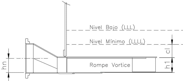

Figure No. 6
Flush Bottom Suction Nozzle with Vortex Breaker.
3.1.2 Low Liquid Level (LLL)
The calculation of the low level (LLL) depends on:
Minimum Level (LLLL)
Maximum Emptying Rate (MER)
Tank Cross Section Area (CSA)
Response Time (TR1)
It is determined with the following equation:
LLL = LLLL + Max[(MER x TR1)/CSA,100]
Where:
TR1 is the response time to stop the discharge pump, defined by the operator or the by customer.
For reference, the TR1 is usually between 5 and 10 minutes.
The difference between LLLL and LLL should not be less than 100 mm.
3.1.3 Normal Operation Level (NOL). See Figure No. 7
The calculation of the normal operating level (NOL) depends on the base capacity defined in the project. This ability can be:
Nominal Capacity (NC)
Maximum Capacity (MC)
Net Working Capacity (NWC)
The sequence of calculation of the levels depending on the required base capacity is shown below:
Nominal Capacity (Case 1)
Freeboard (F)
Critical level (CH)
High high liquid level (HHLL)
Normal operation level (NOL)
o High Level (HLL)
Seismic freeboard (SFB).
Total tank height (H)
Maximum Capacity (Case 2)
Critical level (CH)
High high liquid level (HHLL)
Normal operation level (NOL)
o High Level (HLL)
Freeboard (F)
Seismic freeboard (SFB).
Total tank height (H)
Normal operation level (NOL)
o High Level (HLL)
High high liquid level (HHLL)
Critical level (CH)
Freeboard (F)
Seismic freeboard (SFB).
Total tank height (H)
Net Working Capacity (Case 3)
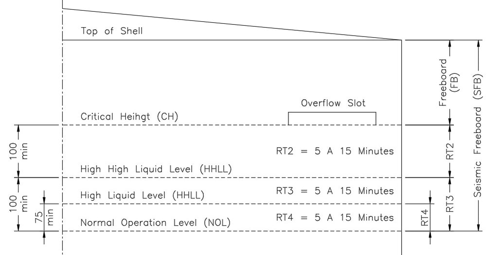
Figure No. 7
Levels and Responses Times.
Depending on the type of base capacity established, the NOL will be determined will be determined using the relevant case method.
3.1.3.1 Case 1. With nominal capacity (NC).
If the calculation is based on nominal capacity (NC), the NOL will depend on:
Critical level (CH).
High High Level (HHLL)
Maximum Fill Flow (MFR)
Response time between CH and HHLL (RT2)
Response time between HHLL and NOL (RT3)
Tank Cross Section Area (CSA)
The equation is:
NOL = CH - Max[(CH – HHLL),100] – Max[(MFR x RT3/CSA),100]
Where:
CH = H - FB, &
HHLL = CH - MFR x RT2/CSA
Additional considerations:
H - FB represents the critical level (CH). H being the height of the tank shell and FB being the freeboard (see section 3.1.7).
API 2350 recommends that the difference between CH and HHLL be at least 75 mm, but 100 mm is suggested as a margin of safety.
It is recommended that the difference between HHLL and NOL be at least 100 mm.
TR2 is the filling time between CH and HHLL, usually between 5 and 15 minutes.
TR3 is the filling time between HHLL and NOL, typically between 5 and 15 minutes.
3.1.3.2 Case 2. With maximum capacity (MC).
If the calculation is based on maximum capacity (MC), the NOL will depend on:
Maximum Fill Flow (MFR)
Response time between CH and HHLL (RT2)
Response time between HHLL and NOL (RT3)
Tank Cross Section Area (CSA)
The equation is:
NOL = CH - Max[(CH – HHLL),100] – Max[(MFR x RT3/CSA),100]
Where:
CH = MC/CSA, &
HHLL = CH - MFR x RT2/CSA
Additional considerations:
MC/CSA represents the critical level (CH).
API 2350 recommends that the difference between CH and HHLL be at least 75 mm, but 100 mm is suggested as a margin of safety.
It is recommended that the difference between HHLL and NOL be at least 100 mm.
TR2 is the filling time between CH and HHLL, usually between 5 and 15 minutes.
TR3 is the filling time between HHLL and NOL, typically between 5 and 15 minutes
3.1.3.3 Case 3. With the net working capacity (NWC).
In this case, the NOL is calculated considering:
· Low Operating Level (LLL)
· Net Operating Capacity (NWC)
· Tank Cross Section Area (CSA)
The equation is:
NOL = LLL + NWC/CSA
3.1.4 Nivel alto (High Liquid Level “HLL”)
The High Level (HLL) is an optional level that can be set as an alarm to alert when the tank exceeds the normal operating level (NOL). It is calculated with the following equation:
HLL = NOL + Max[(MFR x RT4)/CSA,75]
Considerations:
TR4 is the response time between NOL and HLL, recommended at 5 minutes.
The difference between HLL and NOL should not be less than 75 mm to ensure an adequate safety margin.
3.1.5 High High Liquid Level (HHLL)
The High High Liquid Level (HHLL) calculation can be calculated in three ways, depending on the base capacity used:
3.1.5.1 Case 1. With nominal capacity (NC).
In this case, HHLL is determined based on:
Nominal Capacity (NC)
Tank Cross Section Area (CSA)
Maximum Fill Flow (MFR)
Response time between CH and HHLL (RT2)
The equation is:
HHLL = CH – MFR x TR2,
Where:
CH = H – FB, & H = NC/CSA
Additional considerations:
CH represents the critical level. H the height of the tank shell and FB the freeboard (see section 3.1.7).
API 2350 recommends that the difference between CH and HHLL be at least 75 mm, although 100 mm is suggested as a margin of safety.
3.1.5.2 Case 2. With maximum capacity (MC).
In this case, HHLL is determined based on:
Maximum Capacity (MC)
Tank Cross Section Area (CSA)
Maximum Fill Flow (MFR)
Response time between CH and HHLL (RT2)
The equation is:
HHLL = CM/CSA – Max[(MFR x TR2),100]
Additional considerations:
· MC/CSA represents the critical level (CH).
· API 2350 recommends that the difference between CH and HHLL be at least 75 mm, but 100 mm is suggested as a margin of safety.
3.1.5.3 Case 3. With net working capacity (NWC).
Here, the HHLL is calculated by considering:
Net working capacity (NWC).
Normal Operating Level (NOL)
Maximum Fill Flow (MFR)
Response Time (RT3)
Tank Cross Section Area (CSA)
The equation is:
HHLL = NOL + Max[(MFR x RT3)/CSA,100]
NOL = LLL + NWC/CSA
Additional considerations:
API 2350 recommends that the difference between HHLL and NOL be at least 75 mm, but 100 mm is suggested as a margin of safety.
TR3 is the turnaround time to complete fill actions between NOL and HHLL, typically between 5 and 15 minutes.
3.1.6 Critical Level or Critical Height (CH)
The critical level (CH) calculation can be calculated in three way
3.1.6.1 Case 1. With nominal capacity (NC).
In this case, the CH is determined based on:
Nominal Capacity (NC)
Tank Cross Section Area (CSA)
Freeboard (FB), see Part 3.1.7.
The equation is:
CH = NC/CSA - FB
3.1.6.2 Case 2. With maximum capacity (MC).
In this case, the CH is determined based on:
Maximum Capacity (MC)
Tank Cross Section Area (CSA)
The equation is:
CH = CM/CSA
3.1.6.3 Case 3. With the net working capacity (NWC).
Here, the CH is calculated considering:
Net Work Capacity (NWC)
Maximum Fill Flow (MFR)
Response time for filling (RT2)
Response time for filling (RT3)
Tank Cross Section Area (CSA)
The equation is
CH = HHLL + Max[(MFR x RT2)/CSA,100]
Where:
HHLL = NOL + Max[(MFR x RT3)/CSA,100],
& NOL = LLL + NWC/CSA
Additional considerations:
API 2350 recommends that the difference between CH and HHLL be at least 75 mm, but 100 mm is suggested as a margin of safety.
It is recommended that the difference between HHLL and HHLL be at least 75 mm, but 100 mm is suggested as a margin of safety.
TR2 is the response time between CH and HHLL, typically between 5 and 15 minutes.
TR3 is the response time between HHLL and NOL, typically between 5 and 15 minutes.
3.1.7 Freeboard.
Freeboard (FB) varies depending on the type of tank and the accessories installed, such as foam chambers and overflow nozzles. The different cases are presented below:
3.1.7.1 Case 1. Roof Tank without Foam Chamber (See Figure No. 8).
This case applies to fixed-roof tanks and open (roofless) tanks. Freeboard (FB) depends on the nominal diameter of the overflow nozzle (dr) and is calculated with the following equation:
FB = 3 x dr/2
Recommendation:
If the tank does not have an overflow nozzle, a minimum freeboard of 300 to 450mm is recommended.
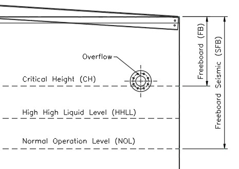
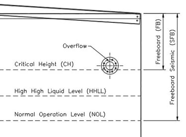
Figura No. 8
Tanque sin Cámara de Espuma
3.1.7.2 Case 2. Fixed roof tank with foam chamber (See Figure No. 9).
In this case, the FB depends on:
Nominal Overflow Nozzle Diameter (dr)
Foam chamber height (F)
Clearance (cl1)
It is determined with the following equation:
FB = Max(FB1,FB2)
Where:
FB1 = 3 x dr/2, & FB2 = F + cl1
Definitions:
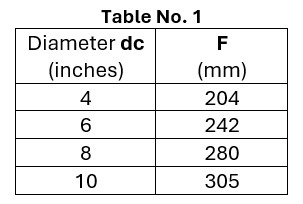
dc = Discharge diameter of the foam chamber
CL1 = DC/2 + 150 mm (with DC in mm)
F = Foam chamber location height (dc) as shown in table No. 1
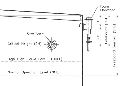
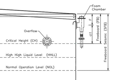
Figure No. 9
Fixed Roof Tank with Foam Chamber

Recommendation:
If the tank does not have an overflow nozzle, a minimum FB1 of 300 to 450 mm is suggested.
3.1.7.3 Case 3. Fixed Roof Tank with Internal Floating Roof (See Figure No. 10).
This case applies to tanks with a conical fixed roof with an aluminum geodesic dome structure and roof, which have a floating inner cover.
Freeboard (FB) depends on:
Nominal Overflow Nozzle Diameter (dr)
Foam chamber height (F)
Clearance (cl1)
Floating Roof Height (frh)
It is determined with the following equation:
FB = Max(FB1,FB2)
Where:
FB1 = 3 x dr/2, & FB2 = F + cl1 + frh
Definitions:
dc = Discharge diameter of the foam chamber (see table No. 1)
Cl1 = DC/2 +150 mm.
F = Foam chamber height (as per table above)
frh = Floating roof height above liquid level (includes total seal height)
Recommendation:
If the tank does not have an overflow nozzle, a minimum FB1 of 300 to 450 mm is suggested,
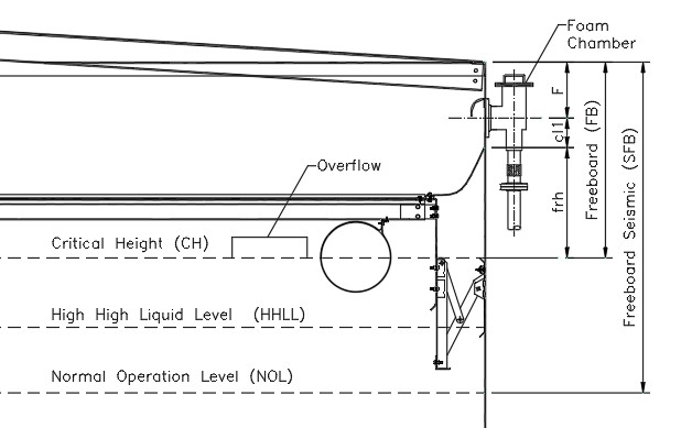
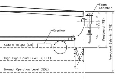
Figure No. 10
Fixed Roof Tank with Internal Floating Roof
3.1.7.4 Case 4. Tank with External Roof (See Figure No. 11).
In tanks with an external floating roof, the freeboard (FB) depends on:
Clearance (cl1)
Floating Roof Height (frh)
It is calculated with the equation:
FB = cl1 + frh
Definitions:
Cl1 = 300 mm.
frh = Floating roof height above liquid level (includes total seal height)
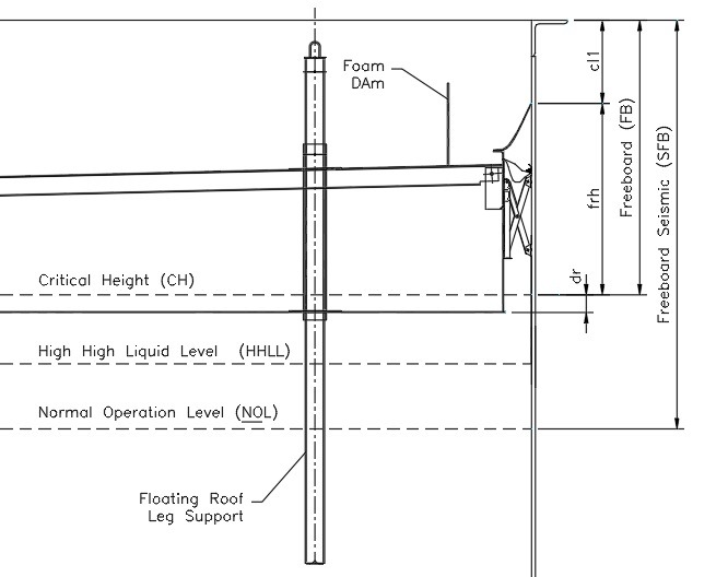
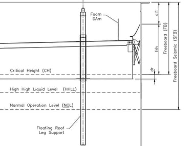
Figure No. 11
Tank with External Floating Roof
3.1.8 Seismic Freeboard (SFB).
Seismic freeboard (SFB) is calculated by considering the seismic wave height (SWH), according to the equation:
SFB = SWH + frh + cl2
Considerations:
SWH is calculated by the tank designer and depends on the site's seismic regulations, soil type, and other factors. Although in our opinion the seismic wave height should be considered for all tanks, the customer, owner or their representative should indicate whether it should be considered.
It is recommended to consider SWH in all tanks that store:
o Essential products to be used after an earthquake.
o Hazardous substances that could pose a risk to public health.
o Flammable liquids, where a spill could cause fires.
frh = Floating roof height above liquid level (includes total seal height)
CL2 = 300mm for fixed roof tanks with internal floating roof and 150 for external floating roof tanks and fixed roof tanks without internal floating roof
3.1.9 Total Height of the Tank Shell (H).
The total height of the tank shell (H) is determined as the greater of:
· The sum of the critical level (CH) and the freeboard (FB).
· The sum of the normal operating level (NOL) and the seismic freeboard (SFB).
It is calculated with the following equations:
H = Max(H1,H2)
Where:
H1 = CH + FB, & H2 = NOL +SFB
3.2 Capacities
Once the operating levels have been established, the different volumetric capacities can be calculated using the tank cross-sectional area (CSA), determined by:
CSA = (π x D^2)/4
3.2.1 Nominal Capacity (NC)
It is the volume of the tank calculated with the product of the tank cross-sectional area and the total shell height (H).
NC = CSA x H
3.2.2 Maximum Capacity (MC)
It is the volume or capacity of the tank calculated with the critical level (CH).
MC = CSA x CH
3.2.3 Minimum Operating Capacity (MOC)
It is the volume of the tank below the low operating level (LLL), which cannot be pumped.
MOC = CSA x LLL
3.2.4 Net Working Capacity (NWC)
It is the volume of liquid between the normal operating level (NOL) and the low level (LLL).
NWC = CSA x (NOL – LLL)
4 Conclusions
1. Importance of Level Control
The correct determination of the operating levels in storage tanks under the API 650 & API 2350 standards is essential to guarantee safety, operational efficiency and risk prevention.
2. Key Factors in Design
Levels such as LLLL, LLL, NOL, HLL, HHLL, and CH are influenced by parameters such as nozzle elevation, fill and empty flow rates, and the response time required for emergency actions.
3. Relevance of API Regulations
Applying standards such as API 650 and API 2350 ensures that tanks meet structural design criteria, overfill control, and overload failure prevention.
4. Impact of External Factors
Aspects such as seismic wave height, pump NPSH, and the location of outlet and overflow nozzles can modify operating levels and should be considered in the design
5. Base Capacity
Defining the base tank capacity is a critical factor in the design and operation of storage systems. It is essential that the customer clearly establishes whether the required capacity will be the nominal, maximum or net working capacity, since from this selection the different levels of operation of the tank are determined.
5 Recommendations
1. Rigorous Design Verification
Before defining the levels of operation, the tank data sheet must be reviewed and validated that the specifications meet the safety and operability requirements.
2. Using Correct and Consistent Formulas
It is essential to correctly apply the equations for calculating levels and capacities, ensuring the correct conversion of units and compatibility with API regulations.
3. Implementation of Overfill Prevention Systems
It is recommended to evaluate the installation of automatic tank gauge systems (ATG) and independent alarms to minimize the risk of overflow and improve remote monitoring, which also reduces operational response times.
4. Consider Seismic and Safety Factors
In areas with seismic activity, an adequate seismic freeboard should be included to contain the impact of splash waves and prevent spills.
5. Training of Operational Personnel
It is crucial for operators to understand the levels of control and response to anomalous events to ensure proper tank handling in normal operating and emergency situations.
6 Final Summary
This blog offers a detailed technical guide for the determination of levels and capacities in storage tanks, following API regulations and should be used in conjunction with the project specifications. The correct implementation of these criteria allows optimizing the operation of the tanks, preventing incidents and ensuring regulatory compliance
7 References and Standards
American Petroleum Institute
API 650: Welded Tanks for Oil Storage.
API 2350: Overfill Prevention for Storage Tanks in Petroleum Facilities.
Details
engineering
info@aceinteca.com
© 2024. All rights reserved.
Technical Information for Tank Equipment Courtesy of World Bridge Industrial Co. Ltd.
Technical Information for Tanks Protection Devices Courtesy of Korea Steel Power Corp.
Technical Information for Bolted Tanks Courtesy of Center Enamel.
Glass Fused Steel Bolted Tanks
Stainless Steel Bolted Bolted Tanks
Aluminum Suspended Deck for Cryogenic Tanks.
Aluminum Rolling Ladder for External Floating Roofs
WhatsApp +58 416 6289796