Calculation of Tank Venting Requirements According to API 2000
Ing. José Félix Acevedo B.
5/5/20254 min read
1 Introduction
Venting systems in atmospheric and low-pressure tanks prevent dangerous pressure or vacuum build-up during normal or emergency conditions. API 2000, harmonized with ISO 28300, defines the criteria for calculating venting requirements under various conditions.
This document presents the different calculation methods, differences between editions, devices involved and the key rules for setting set points, clearly and precisely.
2 Basics
MAWP: Maximum allowance working pressure of the tank.
Set point: Pressure at which a valve begins to open.
Overpressure: Increase needed over the set point to achieve the design flow.
Relief pressure: Sum of set point + overpressure.
Buildup: How much MAWP can be exceeded during relief.
3 Causes of Overpressure or Vacuum.
3.1 Normal Conditions:
Liquid movement (filling and emptying)
Thermal changes (solar and environmental effect)
3.2 Emergency Conditions:
External fire
Operational failures (coil breakage, etc)
4 Factors Affecting the Tank Venting Requirement
Geographic latitude: Defines the Y and C coefficients for thermal respiration.
Thermal insulation: Reduces the required volume of venting.
Product Vapor Pressure: Determines whether the 2.0 factor is applied at expiration.
Tank size and geometry: Affects the mass of displaced gas.
Location and altitude: Air density and ambient pressure conditions change.
5 Calculation Methods
5.1 Liquid Movement
a) For non-volatile products
(Vapor pressure < 5 kPa)
Outbreathing (filling):
Vop = Vpf
Inbreathing (emptying):
Vip = Vpe
Where:
Vop: Required Expiry Flow Rate (Nm³/h)
VIP: Required flow rate of inspiration (Nm³/h)
Vpf: Maximum filling flow rate (Nm³/h)
Vpe: Maximum emptying flow rate (Nm³/h)
b) For volatile products
(Vapor pressure > 5 kPa)
According to API 2000 7th edition, section 3.3.2.2.1.b, the outbreathing (filling) is:
Vop = 2 Vpf
This considers the effect of liquid-vapor imbalance when volatile liquids enter.
Inbreathing (emptying):
Vip = Vpe
5.2 Due to environmental thermal effect
Thermal outbreathing:
VOT = Y Ri Vtk^0.9
Thermal inbreathing:
VIT = C Ri Vtk.^0.7
Where:
Vtk: Geometric Tank Volume (m³)
Y & C: Latitude-dependent coefficients
Ri: Thermal insulation factor (1 uninsulated, <1 insulated)
Latitude and Y and C coefficients:
Geographic latitude significantly affects the requirement for thermal respiration venting, by influencing the daily thermal amplitude. API 2000 classifies latitudes as follows:
Latitude Y C
Below 42° C 0.32 4-6
Between 23° C & 58° C 0.25 3-5
Above 58° C 0.20 2.5-4
Effect of thermal insulation:
The use of insulation reduces thermal effects on the vapor space. The isolation factor Ri typically varies between:
Non-insulated: Ri = 1.0
Partial isolation: Ri = 0.5–0.8
Complete insulation: Ri = 0.3–0.5
5.3 Due to External Fire
This calculation considers the vapor generated by heat transfer due to a nearby fire.
a) Products with Pv similar to hexane:
q = 208.2 F Atws^0.82
Where:
Q: Total heat transferred (W)
F: Insulation correction factor (≈1 if no insulation is present)
Atws: Wet area of the tank exposed to fire (m²)
b) Products with Pv greater than hexane or unknown:
q = 906.6 (Q F/L) (T/M)^0.5
Where:
Q: Absorbed thermal load (kW)
F: Insulation factor
L: Latent heat (kJ/kg)
M: Molar mass (kg/kmol)
T: Relief Temperature (K)
5.4 Appendix A.
Appendix A provides a simplified method for estimating venting requirements under standard operating conditions. This method avoids detailed calculations when certain conditions of applicability are met:
Conditions for applying Appendix A:
The tank must be atmospheric, not refrigerated and above ground level.
Tank volume less than 100,000 barrels (approximately 15,900 m³).
The product should have a vapor pressure of less than 14 psia (approximately 96.5 kPa).
The facility must operate under typical environmental and operating conditions, without abnormal heat sources or special processes.
This method provides tabulated values that simultaneously integrate the effects of liquid movement, thermal breathing, and average conditions for latitude and insulation.
⚠️ Appendix A should not be used for extreme conditions, presence of fire, highly volatile products, or unconventional configurations.
5.5 Other Contingencies
Other contingencies require specific engineering analysis, including the following:
Coiled Breaks
Uncontrolled reflux
Untimely valve closure
Require specific engineering analysis
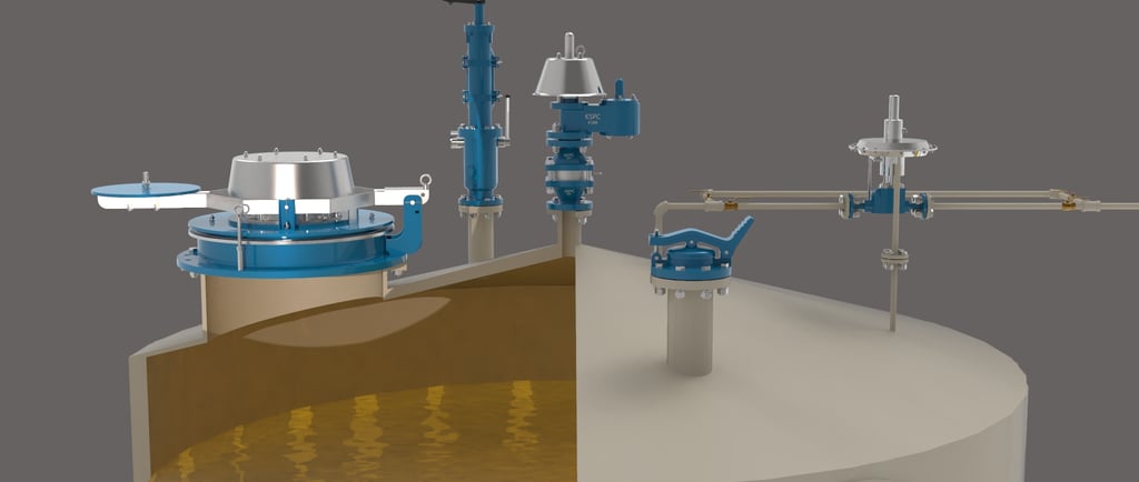
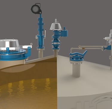
6 Venting Devices
6.1 Pressure and Vacuum Valves (Conservation Valves)
Typical set point range:
0.35–1.4 kPa
0.05–0.2 psig
1.4–5.6 in H₂O
6.2 Emergency Valves
Typical set point range:
1.5–5.0 kPa
0.22–0.73 psig
6–20 in H₂O
6.3 Blanketing Valves
Maintain positive pressure with nitrogen or other gas
Prevents air ingress, oxidation and formation of flammable mixtures
7 Set Point and Devices Staggering
7.1 Relation with Operating Pressure
The set point of the pressure relief valve (conservation valve) must be at least 10% higher than the normal operating pressure of the tank.
7.2 Staggering Between Devices
Relation / Recommendation
Preservation Valve vs. Operating Pressure: / Preservation Valve Set point ≥ 10% higher than operating pressure
Emergency valve vs. Preservation valve: / Emergency valve set point ≥ 10% higher than that of the conservation valve
Emergency Valve vs. MAWP: / Emergency Valve Relief pressure ≤ MAWP (API 650 or API 620)
Example:
Operating Pressure: 10 mbar (0.145 psig)
Set point of preservation: 12 mbar (0.174 psig)
Emergency set point: 15 mbar (0.22 psig)
MAWP API 650 Tank: 17.2 kPa (2.5 psig)
7.3 Limits According to Design Code
Norm: API 650
MAWP: ≤ 2.5 psig (17.2 kPa)
Allowed Accumulation: 0% (cannot be exceeded)
Norm: API 620
MAWP: ≤ 15 psig (17.2 kPa)
Allowed Accumulation: 0% (cannot be exceeded)
8 Comparison: API 2000 6th vs. 7th Edition
The main difference between the 7th and 6th editions of API 2000 lies in the venting requirement for liquid movement (outbreathing) of volatile liquids. Section 3.3.2.2.1.b, specifies that for liquids with vapor pressure above 5 kPa, the required venting rate during filling should be twice the liquid inflow rate. This requirement was not explicitly addressed in the 6th edition.
9 Conclusions
API 2000 provides specific methods for each type of contingency. Therefore, venting calculations should address scenarios such as liquid movement, thermal breathing, or fire individually, using the appropriate methodology for each case.
Proper valve staging and accurate set point selection are essential to prevent product losses, avoid overpressure, and ensure safe operation. This configuration provides effective protection without triggering devices unnecessarily.
Venting devices must be selected in compliance with the tank's MAWP, according to the limits established by API 650 and API 620. Exceeding this value is not recommended under any circumstances.
Appendix A can be useful in simple operational cases but should not replace a full engineering analysis when special conditions or additional risks are present.
Details
engineering
info@aceinteca.com
© 2024. All rights reserved.
Technical Information for Tank Equipment Courtesy of World Bridge Industrial Co. Ltd.
Technical Information for Tanks Protection Devices Courtesy of Korea Steel Power Corp.
Technical Information for Bolted Tanks Courtesy of Center Enamel.
Glass Fused Steel Bolted Tanks
Stainless Steel Bolted Bolted Tanks
Aluminum Suspended Deck for Cryogenic Tanks.
Aluminum Rolling Ladder for External Floating Roofs
WhatsApp +58 416 6289796